
LUX PSD111B
Lux Pro PSD111B Non-Programmable Thermostat User Manual
Model: PSD111B | Brand: LUX
Introduction
This manual provides detailed instructions for the installation, operation, and maintenance of your LUX Pro PSD111B Non-Programmable Thermostat. This thermostat is designed for use with 1 Heat, 1 Cool systems, offering reliable temperature control for your home.

Image: Front view of the Lux Pro PSD111B thermostat, displaying the current temperature and mode on its digital screen, with up/down temperature adjustment buttons and system mode switches on the side.
Setup and Installation
What's in the Box?

Image: Contents of the product packaging, including the thermostat unit, mounting screws, wall anchors, and wire labels for organized installation.
- 1 x LUX Pro PSD111B Thermostat
- 2 x Mounting Screws
- 2 x Wall Anchors
- Wire Labels
- Instruction Manual
Mounting Options
The PSD111B thermostat can be installed in either a horizontal or vertical orientation to suit your wall space and aesthetic preferences.

Image: Diagram illustrating the thermostat's ability to be mounted horizontally or vertically, highlighting its large backlit display and dual power capability (2 AA batteries or 24 VAC).
System Compatibility
This unit is compatible with most 24-volt gas, oil, or electric heating and air conditioning systems, gas millivolt heating systems, and single-stage heat pumps. It is not compatible with 120-volt heating systems or two-stage heat pumps.

Image: A chart detailing system compatibility. It shows the thermostat is compatible with 24V Heat (Gas/Oil/Electric Furnace - Heating only, Single Stage, Heat Pump w/o Auxiliary Heat, 2-wire Hydronic, 750 Millivolt, Gas Fireplaces) and 24V Cool (Cooling only, Single stage cooling). It is not compatible with Heat Pump Multistage, Radiant Ceiling Heat, Electric Baseboards, Heat Pump w/ Auxiliary Heat, Portable space heaters, 3-wire Hydronic, Gas/Oil/Electric Furnace - Multistage, Cool Multistage, or Plug-in air conditioners.
Wiring Diagrams
Refer to the following diagrams for proper wiring connections. Always turn off power to your HVAC system at the circuit breaker before beginning any wiring work.
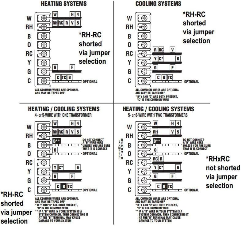
Image: Wiring diagrams for various HVAC configurations, including heating systems, cooling systems, and heating/cooling systems with one transformer. It shows terminal connections for W, RH, B, O, RC, Y, G, C, and jumper selections for RH-RC.

Image: Advanced wiring diagrams for the thermostat, covering typical 2-wire heat hookup, 3-wire heat hookup, 4-wire heating and cooling, 5-wire heating and cooling, and single-stage heat pump configurations. It details connections for gas valves, transformers, and cool compressors.
Important: Ensure the RH-RC jumper is correctly set based on your system's wiring (shorted for single transformer systems, not shorted for two transformer systems).
Power Source
The thermostat operates on 2 AA alkaline batteries (included) or can be powered by a 24-volt AC system. The easy-view backlight requires battery power.
Operating Instructions
Control Panel Overview

Image: A labeled diagram of the thermostat's control panel, indicating the 'TEMP UP' and 'TEMP DOWN' buttons, the 'MODE' switch (HEAT, OFF, COOL), and the 'FAN MODE' switch (ON, AUTO).
- TEMP UP/DOWN Buttons: Adjust the desired temperature setting.
- MODE Switch: Select the system operation mode:
- HEAT: Activates the heating system.
- OFF: Turns off both heating and cooling systems.
- COOL: Activates the cooling system.
- FAN MODE Switch: Controls the fan operation:
- ON: The fan runs continuously.
- AUTO: The fan runs only when the heating or cooling system is active.
Temperature Display
You can choose to display the temperature in either Fahrenheit (°F) or Celsius (°C). Refer to the internal settings or specific instructions for switching between these units.
Adjustable Temperature Swing (Differential)
The thermostat features a 9-step adjustable temperature swing setting. This allows you to control the temperature differential (the difference between when the system turns on and off) for precise comfort management. A smaller swing results in more frequent, shorter cycles, while a larger swing results in less frequent, longer cycles.
High and Low Temperature Limits
Set adjustable high and low temperature limits to prevent the system from heating or cooling beyond a desired range, ensuring energy efficiency and comfort.
Compressor Delay
The thermostat includes a 2 or 5-minute compressor delay to protect your cooling system from short cycling. There is also a test mode to temporarily disable this delay for installation or diagnostic purposes.
Maintenance
Battery Replacement
The thermostat requires 2 AA alkaline batteries. When the battery indicator appears on the display, replace both batteries promptly to ensure continuous operation and maintain the backlight function. To replace, carefully remove the thermostat from its wall plate and insert new batteries according to the polarity markings.
Cleaning
Clean the thermostat's exterior with a soft, damp cloth. Do not use abrasive cleaners or solvents, as these can damage the unit.
Troubleshooting
If you experience issues with your thermostat, review the following common problems and solutions:
- No Display or Low Battery Indicator: Replace the 2 AA batteries. Ensure they are inserted with correct polarity.
- System Not Responding (Heating/Cooling):
- Check if the system mode switch is set to HEAT or COOL.
- Verify that the desired temperature is set above (for heat) or below (for cool) the current room temperature.
- Ensure the circuit breaker for your HVAC system is not tripped.
- Confirm proper wiring connections, especially the RH-RC jumper.
- Fan Not Running:
- If the fan switch is set to AUTO, the fan will only run when heating or cooling is active. Set to ON for continuous operation.
- Check fan wiring connections.
- Inaccurate Temperature Reading: Ensure the thermostat is not exposed to direct sunlight, drafts, or heat sources that could affect its sensor.
- Short Cycling (System turns on/off too frequently): Adjust the temperature swing setting to a larger differential.
If problems persist after attempting these solutions, contact LUX customer support or a qualified HVAC technician.
Specifications
| Feature | Detail |
|---|---|
| Brand | LUX |
| Model Name | PSD111B-010 |
| Product Dimensions | 1"D x 3.5"W x 4.7"H |
| Controller Type | Push Button |
| Special Feature | Low Voltage |
| Color | White |
| Specific Uses For Product | Air Conditioner, Heat Pump |
| Temperature Control Type | Manual |
| Included Components | PSD111B-010 Mechanical Non-Programmable Thermostat |
| Power Source | AC/DC (2 AA batteries required) |
| Item Weight | 6.4 Ounces |
| Voltage | 24 Volts |
| Material | Plastic |
| Shape | Rectangular |
| Display Type | LCD |
| Control Type | Button Control |
| Mounting Type | Wall Mount |
| Backlight | Yes (Easy-view backlight) |
| UPC | 021079031115 |
| Date First Available | May 5, 2005 |
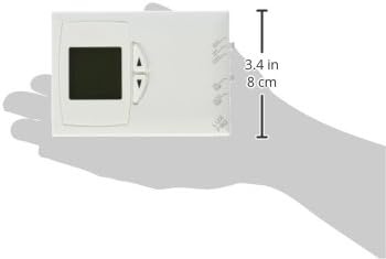
Image: A hand holding the thermostat, illustrating its physical dimensions, specifically a height of 3.4 inches (8 cm).
Warranty Information
The LUX Pro PSD111B Thermostat comes with a 5-Year Limited Warranty. Please retain your proof of purchase for warranty claims. For specific terms and conditions of the warranty, refer to the documentation included with your product or visit the official LUX website.
Customer Support
For technical assistance, troubleshooting, or further inquiries regarding your LUX Pro PSD111B Thermostat, please visit the official LUX website or contact their customer support department. Contact information can typically be found on the manufacturer's website or in the product packaging.
You can also visit the LUX Store on Amazon for more product information and resources.
Related documentsPSD111B


Ask a question about this manual
Ask about setup, troubleshooting, compatibility, parts, safety, or missing instructions. Manuals+ will review the question and use this page’s manual context to help answer it.