
1. Introduction
The SINOTIMER SVP719-1-40A is a versatile 3-in-1 adjustable voltage surge protector designed to safeguard electrical equipment from over-voltage, under-voltage, and over-current conditions. It also features an integrated consumption kWh meter for monitoring energy usage. This device provides automatic recovery, ensuring continuous protection and minimizing downtime. Its compact design and DIN rail mount make it suitable for various applications.
2. Safety Information
- Installation must be performed by qualified personnel in accordance with local electrical codes and regulations.
- Ensure the power supply is disconnected before installation, wiring, or maintenance to prevent electric shock.
- Verify correct voltage and current settings for your application to avoid damage to the device or connected equipment.
- Do not operate the device if it appears damaged or malfunctions.
- The device housing is made of flame-retardant PC material; however, proper ventilation should be maintained.
3. Product Features
- 3-in-1 Protection: Combines over-voltage, under-voltage, and over-current protection in a single unit.
- Integrated kWh Meter: Displays real-time voltage, current, and energy consumption (kWh).
- Automatic Recovery: Automatically restores power when voltage returns to normal after a fault.
- Adjustable Parameters: Overvoltage value, undervoltage value, overcurrent protection, and fault recovery delay time are user-adjustable.
- Durable Construction: Made from flame-retardant and high-quality PC material for impact resistance and long operational life.
- Easy Installation: Equipped with a universal DIN 35mm standard guide rail for quick and secure mounting.
- Clear Status Display: Three digital displays provide clear visibility of circuit status.

Figure 1: SINOTIMER SVP719-1-40A highlighting its core features.
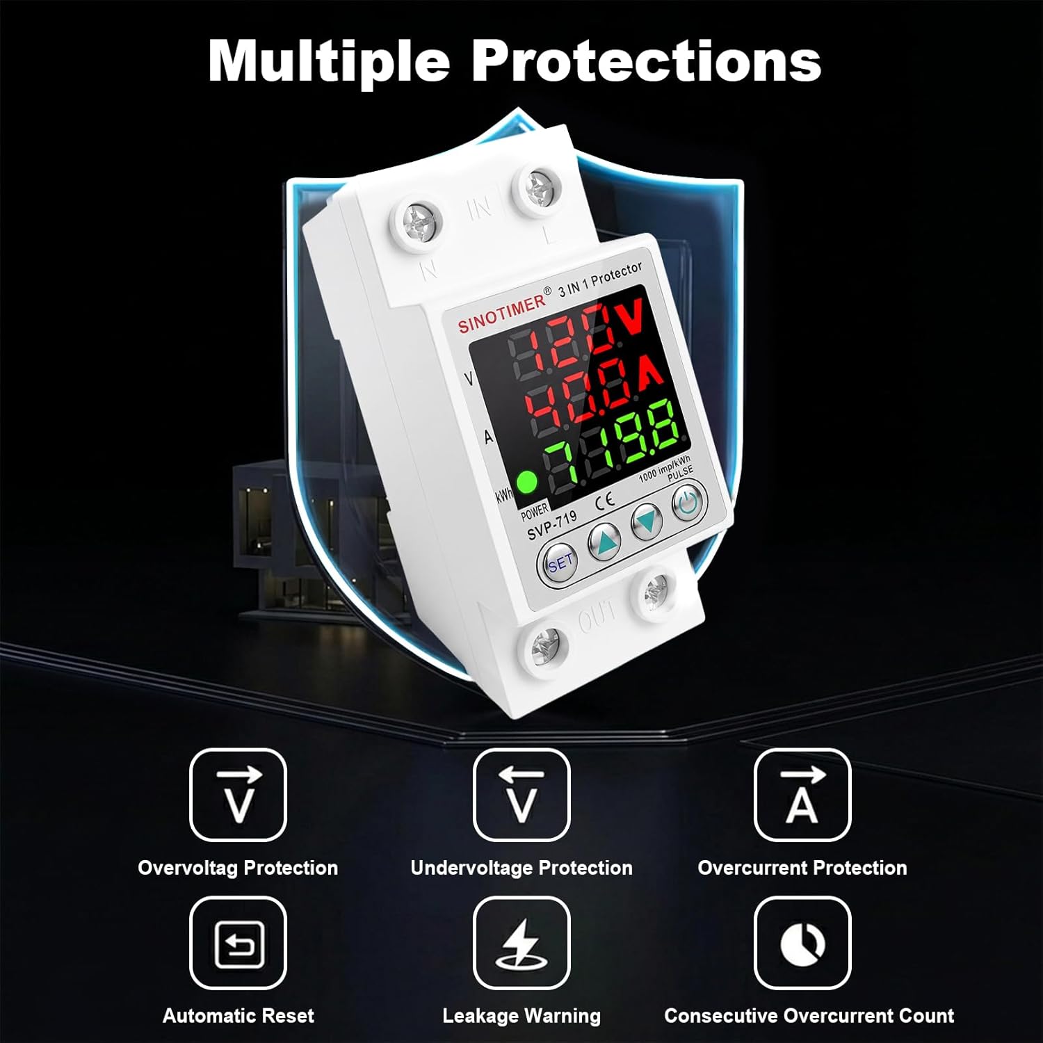
Figure 2: Overview of the multiple protection functions provided by the device.
4. Specifications
| Parameter | Value |
|---|---|
| Model | SVP719-1-40A |
| Rated Frequency | 50/60 Hz |
| Electric Current (A) | 1-40A |
| Overvoltage Protection Range | 130-300V |
| Undervoltage Protection Range | 80-210V |
| Reset/Start Delay | 1s-600s |
| Current Rating | 40 Amps |
| Coil Voltage | 110 Volts (AC) |
| Mounting Type | DIN Rail Mount |
| Contact Material | Silver |
| Operation Mode | Automatic |

Figure 3: Device dimensions and key electrical parameters.
5. Installation
The SVP719-1-40A is designed for easy installation on a standard 35mm DIN rail. Follow these general guidelines:
- Power Disconnection: Always ensure the main power supply is completely disconnected before beginning any installation work.
- Mounting: Snap the device onto a 35mm DIN rail securely. The rail-type buckle ensures a firm fit.
- Wiring: Connect the input (IN) and output (OUT) terminals according to the wiring diagram. The terminal posts are made of copper for good conductivity. Applicable wire sizes are 16-25mm² / 6AWG-4AWG. Ensure all connections are tight and secure.
- Verification: After wiring, double-check all connections for correctness and ensure no loose wires.

Figure 4: Product wiring diagram. De-energize circuit before wiring. Follow diagram exactly. Verify voltage/current settings. Use proper wire size and torque terminals.

Figure 5: Close-up of easy wiring terminals and DIN rail buckle.
6. Operation
6.1 Display Overview
The device features three digital displays for real-time monitoring:
- Voltage (V): Shows the current line voltage.
- Current (A): Displays the current load.
- Energy (kWh): Indicates accumulated energy consumption.
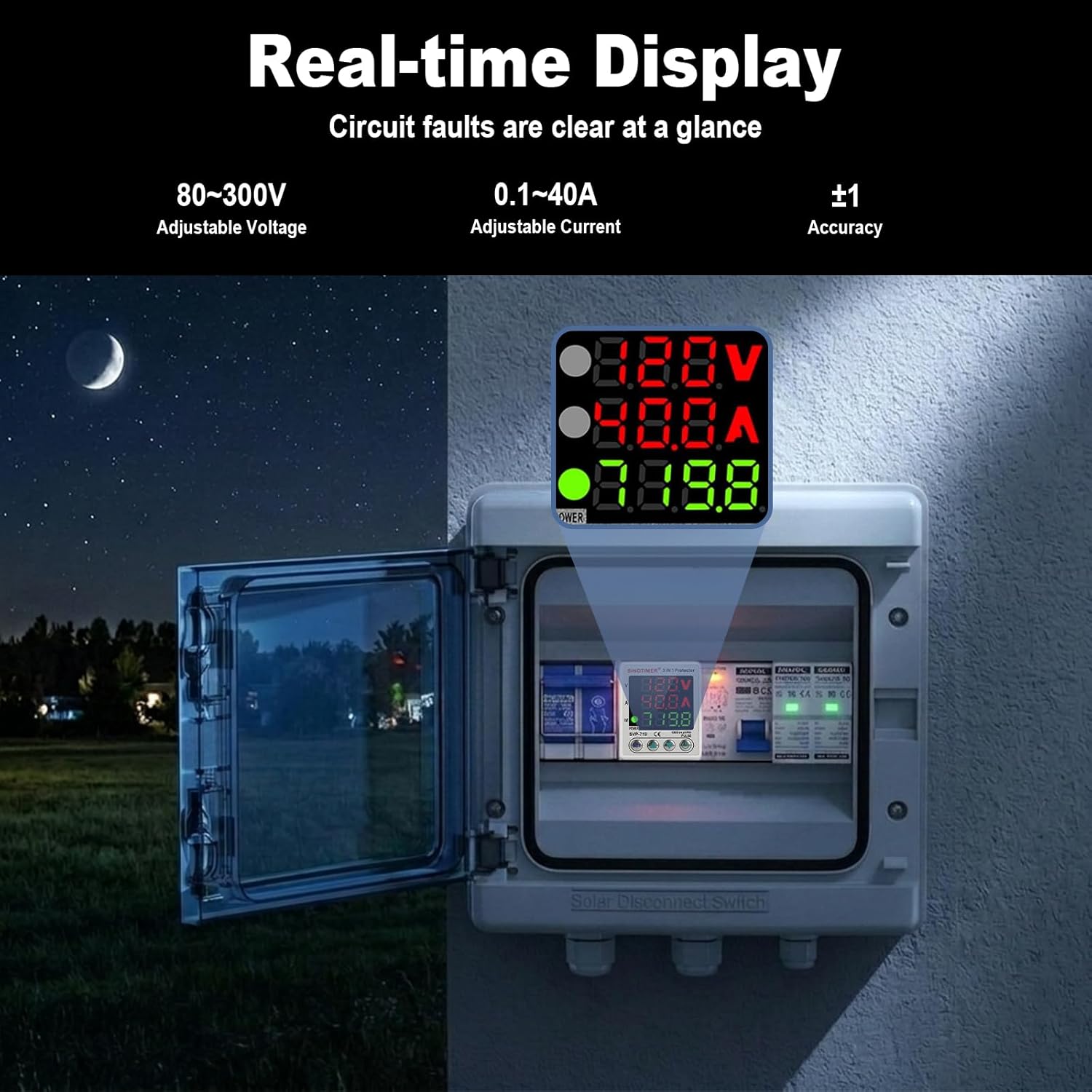
Figure 6: Real-time display of voltage, current, and kWh.
6.2 Setting Parameters
Use the 'SET' button and arrow keys to adjust protection parameters. Press 'SET' to cycle through parameters. Use the up/down arrow keys to change values. The device will automatically save settings after a few seconds of inactivity.
Video 1: This video demonstrates how to navigate and adjust the various protection parameters on the SINOTIMER SVP719-1-40A device, including power-on delay, protection recovery delay, over-voltage/under-voltage settings, current protection, and reset options.

Figure 7: Button controls for menu navigation and value adjustment.
6.3 General Operation
Once installed and configured, the device operates automatically. It continuously monitors voltage and current. If a parameter exceeds or falls below the set limits, the protector will instantaneously cut off the power supply to protect connected equipment. When conditions return to normal, the device will automatically re-engage the power supply after the set recovery delay time.
Video 2: This video provides a general overview of the SINOTIMER Adjustable Voltage Surge Protector Relay, showing its real-time display of voltage and current during operation.
7. Troubleshooting
| Problem | Possible Cause | Solution |
|---|---|---|
| Device does not power on. | No input power; incorrect wiring. | Check main power supply. Verify wiring connections according to the diagram. |
| Power cuts off frequently. | Voltage/current outside set limits; sensitive protection settings. | Check actual voltage/current. Adjust over/under voltage or overcurrent protection values if necessary, ensuring they are appropriate for your system. |
| Device does not reset automatically. | Fault condition persists; recovery delay set too long. | Ensure the fault condition (over/under voltage, overcurrent) has cleared. Check the protection recovery delay setting. |
| Incorrect voltage/current readings. | Calibration error. | Refer to the operation section for calibration procedures. |
8. Maintenance
The SINOTIMER SVP719-1-40A requires minimal maintenance. Periodically inspect the device and its connections:
- Ensure all wiring connections remain tight and free from corrosion.
- Keep the device clean and free from dust and debris.
- Verify that the digital displays are functioning correctly and showing accurate readings.
- Do not attempt to open or repair the device yourself. Refer to qualified service personnel for any issues beyond basic troubleshooting.
9. Warranty and Support
This SINOTIMER product is covered by a 1-Year Manufacturer's Warranty from the date of purchase. This warranty covers defects in materials and workmanship under normal use.
For warranty claims, technical support, or further assistance, please contact SINOTIMER customer service through your purchase platform or the official SINOTIMER website. Please have your model number (SVP719-1-40A) and proof of purchase ready when contacting support.


