1. Introduction and Overview
This document provides comprehensive instructions for the Pingequa Flipper Zero 2-in-1 RF Devboard, an ultra-compact, high-performance wireless module designed for the Flipper Zero GPIO interface. It combines both nRF24L01P (2.4GHz) and CC1101 (433MHz) chips on a single board, offering auto-switching logic without requiring manual toggling or module replacement.
The module is optimized for stable performance, low power consumption, and long-range, low-noise communication, making it suitable for RF research, testing, and educational development projects.
2. What's in the Box
- 1 × NRF24 + CC1101 2-in-1 Module
- 2 × External Antennas (2.4GHz & 433MHz)
- 1 × 3D Printed Case
- 1 × User Guide
Video: Unboxing for Flipper Zero RF 2in1 Module
This video demonstrates the unboxing process of the Flipper Zero RF 2-in-1 module, showing the contents included in the package.
3. Firmware Requirements
This module is specifically optimized for Momentum Firmware. Using official Flipper Zero firmware or other forks without GPIO remapping support will result in the hardware not being detected or functioning correctly.
4. Setup and Installation
Follow these steps to properly configure your Pingequa 2-in-1 RF Devboard with your Flipper Zero:
- Attach the 2-in-1 board to your Flipper Zero's GPIO pins.
- Open the Momentum menu on your Flipper Zero.
- Navigate to: Start → Protocols → GPIO Pins.
- Locate the NRF24 SPI setting and change it to Extra 7. (The CC1101 is controlled via Pin 4).
- Save the settings.
Your Flipper Zero is now configured to recognize and utilize both the NRF24 and CC1101 modules.

Image: Module Connected to Flipper Zero
This image shows the Pingequa 2-in-1 RF Devboard securely attached to the Flipper Zero device, ready for configuration.

Image: Back View of the Module
A detailed view of the back of the 2-in-1 RF Devboard, highlighting its compact design and GPIO pins.
Video: Setting and Using for RF 2in1 NRF24&CC1101 Module
This video provides a step-by-step guide on how to set up and use the RF 2-in-1 NRF24 & CC1101 module with Flipper Zero, including the necessary firmware configurations.
Video: Unbox And Setting for CC1101 Module
This video demonstrates the unboxing and initial setup of a CC1101 module, which is part of the 2-in-1 devboard functionality.
Video: Install Guide for M5Stick C RF 2in1 Module
This video shows an installation guide for a similar RF 2-in-1 module on an M5Stick C device. While not Flipper Zero, it illustrates the physical connection process.
5. Operating Instructions
Once configured, you can switch between NRF24 and Sub-GHz functions directly through the Flipper Zero application interface. The auto-switching logic ensures seamless operation without manual intervention.
Ensure that any applications you use with the module support custom GPIO/SPI settings, as legacy apps with hardcoded pin definitions may not function correctly with this optimized setup.
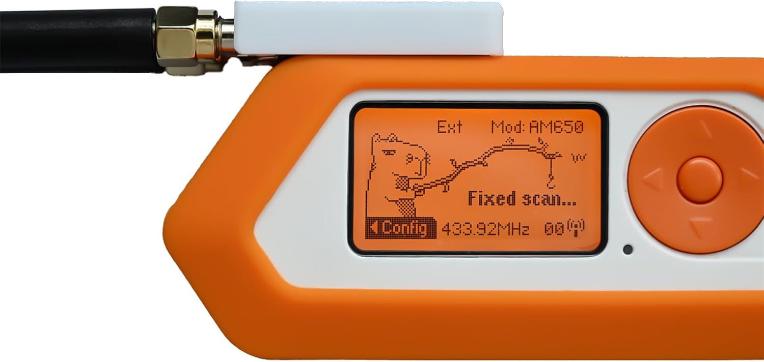
Image: Flipper Zero Screen with Module
The Flipper Zero display showing the interface with the 2-in-1 module connected, indicating active functions or settings.

Image: NRF24 Scan Results on Flipper Zero
A close-up of the Flipper Zero screen showing data from an NRF24 scan, demonstrating the module's 2.4GHz capabilities.

Image: CC1101 Scan Results on Flipper Zero
The Flipper Zero screen displaying data from a CC1101 scan, illustrating the module's 433MHz capabilities.
6. Technical Specifications
- Model Name: NRF24&CC1101 RF 2in1 Module
- Connectivity Technology: GPIO
- Operating System: Linux (compatible with Flipper Zero's underlying OS)
- Package Dimensions: 4.25 x 2.99 x 1.26 inches
- Item Weight: 1.44 ounces
- Manufacturer: PINGEQUA

Image: Module Dimensions
An illustration detailing the physical dimensions of the 2-in-1 RF Devboard, showing its compact size.
7. Maintenance
To ensure the longevity and optimal performance of your 2-in-1 RF Devboard, follow these maintenance guidelines:
- Keep the module clean and dry. Avoid exposure to moisture or extreme temperatures.
- Handle the module with care to prevent damage to the GPIO pins or antenna connectors.
- Store the module in its 3D printed protective case when not in use to prevent physical damage.
8. Troubleshooting
If you encounter issues with your 2-in-1 RF Devboard, consider the following:
- Module Not Detected: Ensure you are running Momentum Firmware on your Flipper Zero. Verify that the NRF24 SPI setting is changed to "Extra 7" in the GPIO Pins protocol settings.
- Application Incompatibility: Some legacy applications may have hardcoded pin definitions that are not compatible with this module's optimized GPIO mapping. Use applications that support custom GPIO/SPI settings.
- Antenna Connection: Ensure both 2.4GHz and 433MHz external antennas are securely attached to their respective ports for optimal signal performance.
Video: FIX: CC1101 & NRF24 "Not Found" Error on M5StickC Plus (Bruce Firmware v1.13)
This video addresses a common "Not Found" error for CC1101 and NRF24 modules on M5StickC Plus, which may offer insights for similar issues with the Flipper Zero module, particularly regarding firmware and pin configurations.
9. Warranty and Support
For warranty information, technical support, or further assistance, please refer to the product packaging or contact Pingequa customer service directly. Keep your purchase receipt for warranty claims.


