1. Introduction
This manual provides detailed instructions for the safe and effective use of your NJTY Non-Contact Voltage Tester, Model T-03A. This device is designed for non-contact detection of AC voltage, offering a safe method for identifying live wires, checking for circuit breaks, and performing general electrical troubleshooting.

Image 1: NJTY Non-Contact Voltage Tester, Model T-03A. This image shows the overall design of the voltage tester, highlighting its compact and pen-like form factor with a red and black casing, green and red buttons, and an integrated LED flashlight at the tip.
2. Safety Information
Always adhere to local safety regulations and practices when working with electricity. This device is designed to enhance safety, but it does not replace proper electrical safety procedures. Failure to follow these instructions may result in electric shock, injury, or death.
- Do not use the tester if it appears damaged or is not operating correctly.
- Verify the tester's functionality on a known live circuit before and after each use.
- Always wear appropriate personal protective equipment (PPE), such as insulated gloves and safety glasses.
- Do not exceed the specified voltage range (12V-1000V AC or 48V-1000V AC).
- Keep fingers behind the finger guard during operation.
- Avoid direct contact with live conductors. This is a non-contact device.
- Do not use the device in wet conditions or in explosive atmospheres.
- The integrated laser pointer should not be aimed directly at eyes or reflective surfaces.
3. Product Overview
Familiarize yourself with the components of your voltage tester:

Image 2: Diagram illustrating the key components of the NJTY Voltage Tester. Labels include the NCV sensor head (probe), laser pointer, flashlight, signal/indicator lights, high/low signal indicator, power button, sensitivity switch (H/L), lighting/laser switch, and battery cover.
- Probe (NCV Sensor Head): Detects AC voltage without contact.
- Laser Pointer: Emits a red laser for targeting test points.
- Flashlight: Provides illumination in low-light conditions.
- Signal / Indicator: Visual indication of voltage detection.
- High/Low Signal Indicator: Displays the detected voltage level.
- Power Button: Turns the device on and off.
- Sensitivity Switch (H/L): Toggles between high and low sensitivity modes.
- Lighting / Laser Switch: Activates the flashlight or laser pointer.
- Battery Cover: Access point for battery replacement.
4. Setup
4.1 Battery Installation
The NJTY Voltage Tester requires two AAA batteries (included). To install or replace batteries:
- Unscrew the battery cover at the bottom of the tester (refer to Image 2, item 9).
- Insert two 1.5V AAA batteries, ensuring correct polarity (+/-).
- Replace the battery cover and screw it securely.

Image 3: Close-up view of the battery cover at the base of the NJTY Voltage Tester, showing how it can be unscrewed for battery access.
5. Operating Instructions
5.1 Power On/Off
- To power on, press and hold the Power Button (refer to Image 2, item 6) until the indicator lights illuminate.
- To power off, press and hold the Power Button again. The device will also automatically shut down after five minutes of inactivity to conserve battery life.
5.2 Sensitivity Modes
The tester features two sensitivity modes for different applications:
- High Sensitivity Mode (12V-1000V AC): Suitable for detecting lower voltages or for general detection. Press the Sensitivity Switch (H/L) (refer to Image 2, item 7) to select this mode.
- Low Sensitivity Mode (48V-1000V AC): Ideal for detecting higher voltages or when precise localization is needed to avoid false positives from adjacent wires. Press the Sensitivity Switch (H/L) to select this mode.

Image 4: Comparison of high and low sensitivity modes. The top row shows high sensitivity (12-1000V) detecting live wire and null wire. The bottom row shows low sensitivity (48-1000V) detecting live wire and null wire, demonstrating how the tester indicates voltage presence with visual and audible alerts.
5.3 Non-Contact Voltage (NCV) Detection
To detect AC voltage:
- Turn on the tester and select the desired sensitivity mode.
- Place the Probe (NCV Sensor Head) near the conductor, outlet, or device you wish to test.
- If AC voltage is detected, the tester will emit an audible alarm and the Signal / Indicator lights will illuminate, with the High/Low Signal Indicator showing the relative strength of the detected field.

Image 5: The voltage tester in use, demonstrating NCV detection on an electrical outlet and a wire. It also shows the buzzer alarm, flashlight illuminating a circuit box, and the laser pointer targeting a ceiling light.
5.4 Breakpoint Testing
This feature helps locate breaks in live wires:
- Ensure the wire is live and the tester is in an appropriate sensitivity mode.
- Move the Probe (NCV Sensor Head) along the length of the wire.
- The tester will indicate voltage up to the point of the break. The absence of a signal beyond a certain point indicates a break in the circuit.

Image 6: Illustration of breakpoint testing. The tester indicates voltage on one side of a broken wire, and no voltage on the other side, pinpointing the location of the break.
5.5 Flashlight
To activate the integrated LED flashlight for illuminating dark work areas:
- Press the Lighting / Laser Switch (refer to Image 2, item 8) once.
- Press it again to turn off the flashlight.

Image 7: The integrated LED flashlight of the voltage tester illuminating a dark electrical panel, demonstrating its utility in low-light environments.
5.6 Laser Pointer
To activate the laser pointer for precise targeting:
- Press and hold the Lighting / Laser Switch (refer to Image 2, item 8) for a few seconds.
- Release the button to turn off the laser pointer.
- Caution: Do not stare into the laser beam or point it at people or animals.
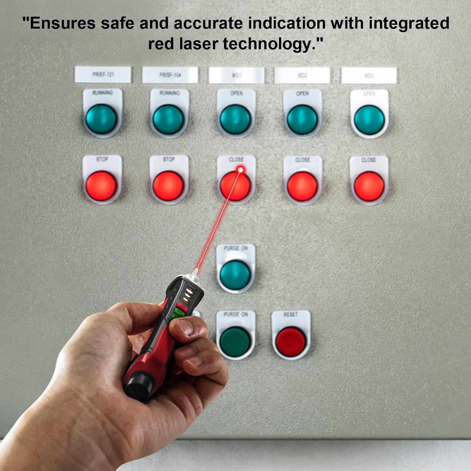
Image 8: A hand holding the voltage tester, using its red laser pointer to indicate a specific button on an electrical control panel, highlighting its precision targeting capability.
6. Maintenance
- Cleaning: Wipe the device with a dry, soft cloth. Do not use abrasive cleaners or solvents.
- Storage: Store the tester in a cool, dry place, away from direct sunlight and extreme temperatures. If storing for extended periods, remove the batteries to prevent leakage.
- Battery Replacement: Replace batteries promptly when the low battery indicator appears to ensure accurate readings.
7. Troubleshooting
| Problem | Possible Cause | Solution |
|---|---|---|
| Tester does not power on. | Dead or incorrectly installed batteries. | Check battery polarity; replace batteries. |
| No detection on a known live circuit. | Low battery, incorrect sensitivity mode, or device malfunction. | Replace batteries, switch to high sensitivity mode (12V-1000V), or contact customer support. |
| False positives (detects voltage where none exists). | High sensitivity mode in a noisy electrical environment. | Switch to low sensitivity mode (48V-1000V). |
8. Specifications
| Feature | Detail |
|---|---|
| Model | T-03A |
| Brand | NJTY |
| AC Voltage Range | 12V-1000V (High Sensitivity), 48V-1000V (Low Sensitivity) |
| Frequency | 50/60Hz |
| Power Source | 2 x 1.5V AAA Batteries |
| Auto Power-Off | After 5 minutes of inactivity |
| Indicators | Audible alarm, LED indicator lights |
| Additional Features | Integrated LED flashlight, Laser pointer, Breakpoint testing |
| Product Dimensions | 0.1 x 0.1 x 0.1 inches |
| Item Weight | 1.8 Ounces |
9. What's in the Box
- 1 x NJTY Voltage Tester Pen
- 2 x 1.5V AAA Batteries
- 1 x English Manual (This document)
10. Warranty and Support
NJTY provides comprehensive after-sales support for sixty months from the date of purchase. If you encounter any issues with your NJTY Non-Contact Voltage Tester, Model T-03A, please contact our customer service team for assistance. Please refer to your purchase documentation for specific contact details.


