1. Introduction
This manual provides detailed instructions for the assembly and operation of the PEMENOL GY21863 Digital Alarm Clock Soldering Kit. This kit is designed for individuals interested in electronics and soldering practice, offering a functional digital clock upon successful assembly. The completed device features time, date, and day of the week display, along with countdown, count-up, and alarm functions.
2. Product Overview
The PEMENOL GY21863 is a versatile electronic kit that combines soldering practice with the utility of a multi-functional digital clock.
2.1 Key Features
- Multifunction Soldering Practice Kit: Ideal for learning and practicing soldering techniques.
- 6-Digit Digital Display: Shows current time, date, and day of the week.
- Timer Functions: Includes count-up (stopwatch) and countdown modes (preset options: 1 hour, 30 minutes, 15 minutes, 5 minutes).
- Alarm Function: Features an alarm with adjustable 7-color LED lighting and sound alerts.
- Adjustable LED Lighting: Control brightness and flashing speed of the 7-color LEDs.
2.2 Components
The kit includes various electronic components, printed circuit boards (PCBs), and hardware necessary for assembly.
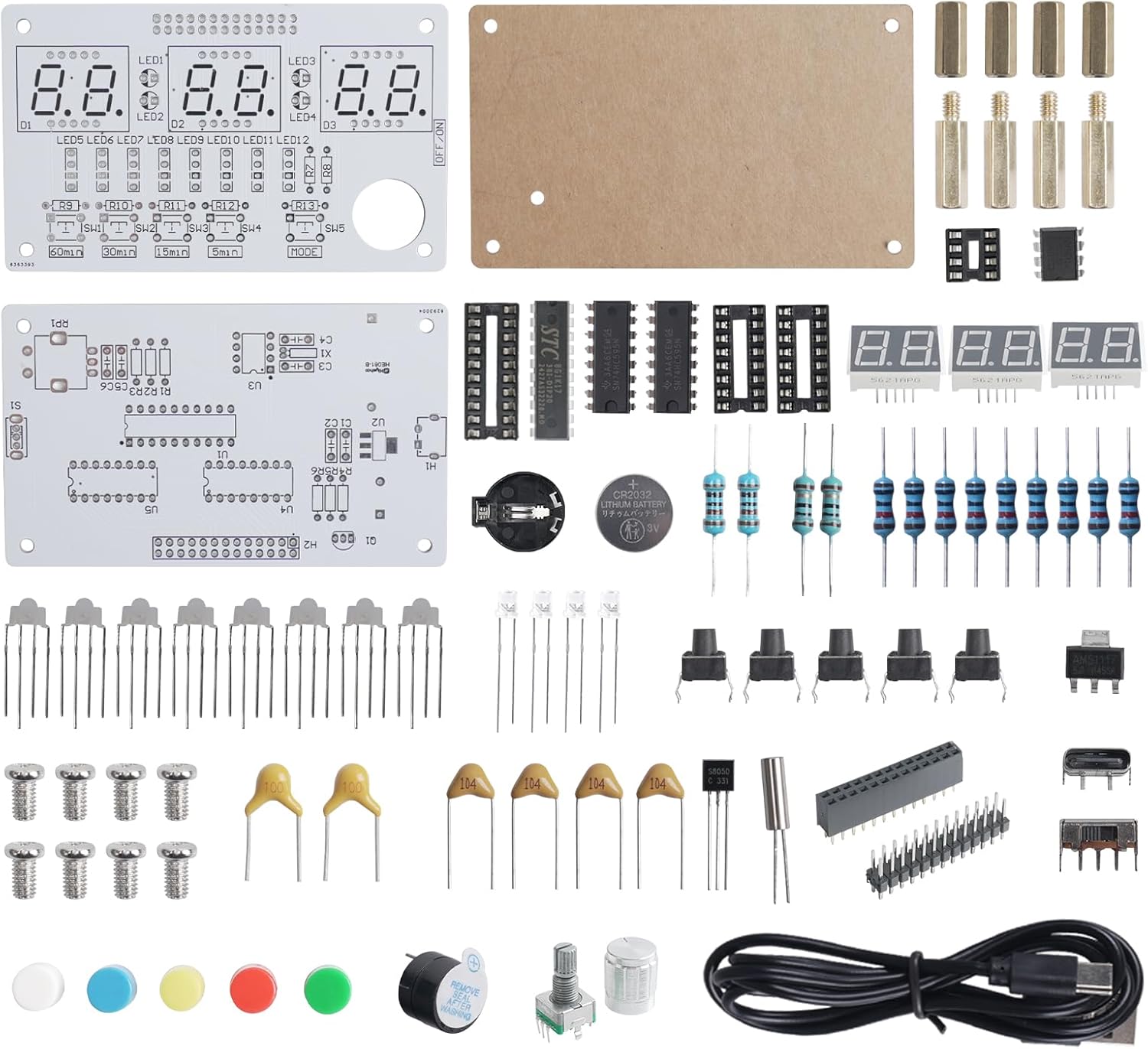
Image 2.1: Overview of the PEMENOL GY21863 Digital Alarm Clock Soldering Kit components. This image displays the various electronic parts, including resistors, capacitors, integrated circuits, LEDs, push buttons, a rotary encoder, a USB cable, and the main circuit boards, all neatly laid out before assembly.

Image 2.2: The fully assembled PEMENOL GY21863 Digital Alarm Clock. This image shows the completed device with its six-digit green LED display, five control buttons (SW1-SW5), a rotary knob, and an ON/OFF switch, housed within a clear acrylic casing.
3. Setup and Assembly
This kit requires soldering for assembly. Basic soldering tools (soldering iron, solder, desoldering wick/pump, safety glasses) are necessary and not included.
3.1 Assembly Steps
- Component Identification: Before starting, identify all components using the provided component list and circuit diagram.
- Solder Smallest Components First: Begin by soldering smaller components like resistors and diodes, followed by capacitors, IC sockets, and then larger components such as buttons, LED displays, and the rotary encoder.
- Observe Polarity: Pay close attention to the polarity of components like diodes, LEDs, and integrated circuits. Incorrect orientation can damage components or prevent the device from functioning.
- Solder Joints: Ensure all solder joints are clean, shiny, and form a good connection without bridging adjacent pads.
- Install ICs: Once all soldering is complete, carefully insert the integrated circuits into their respective sockets, ensuring correct orientation.
- Assemble Casing: Mount the assembled PCB into the acrylic casing using the provided screws and standoffs.

Image 3.1: An individual engaged in the soldering process, demonstrating the hands-on nature of assembling the electronic kit. This highlights the practical learning aspect of the product.
4. Operating Instructions
After successful assembly, connect the device to a 5V USB power source using the provided cable. Use the ON/OFF switch to power on the device.

Image 4.1: Diagram illustrating the control layout of the PEMENOL Digital Alarm Clock. It shows the five push buttons (SW1-SW5) for mode switching and the rotary knob for time/setting adjustments, along with the digital display and LED indicators.
4.1 Control Buttons and Knob
- SW1-SW5 Buttons: Used to switch between the six main display modes (Time, Date, Weekday, Alarm, Timer, Brightness Control).
- Rotary Knob: Used for setting time/wake-up time, starting/pausing timers, and adjusting LED brightness/flashing speed.
4.2 Display Modes
The device supports six distinct display modes, accessible via the SW buttons.

Image 4.2: Visual representation of the six display modes available on the PEMENOL Digital Alarm Clock. These include Time Display, Date Display, Weekday Display, Alarm Mode, Timer Mode, and Brightness Controller.
- Time Display: Shows current hours, minutes, and seconds.
- Date Display: Shows current year, month, and day.
- Weekday Display: Shows the current day of the week.
- Alarm Mode: Allows setting and activating the alarm. When the alarm triggers, the 7-color LEDs will light up and flash, accompanied by an audible alert.
- Timer Mode: Offers both count-up (stopwatch) and countdown functionalities. Preset countdown options include 5, 15, 30, and 60 minutes.
- Brightness Controller: Adjusts the brightness and flashing speed of the 7-color LEDs.
4.3 Setting Time and Date
Specific instructions for setting time and date are typically provided in the detailed product manual. Generally, this involves entering a setting mode using one of the SW buttons and then using the rotary knob to adjust values.
4.4 Using Timer Functions
Navigate to the Timer Mode using the appropriate SW button.
- Countdown: Select a preset countdown (5, 15, 30, or 60 minutes) or set a custom time using the rotary knob. Press the knob to start/pause.
- Count-up (Stopwatch): In this mode, the display will count upwards. Press the knob to start/pause.

Image 4.3: Examples demonstrating the practical applications of the timer function, such as timing for brushing teeth (5 minutes), cleaning (15 minutes), exercise (30 minutes), and reading (60 minutes).
5. Maintenance
To ensure the longevity and proper functioning of your PEMENOL GY21863 Digital Alarm Clock, follow these maintenance guidelines:
- Cleaning: Use a soft, dry cloth to clean the exterior of the device. Avoid using abrasive cleaners or solvents, which can damage the acrylic casing or electronic components.
- Power Source: Always use a stable 5V USB power source. Avoid connecting to power sources with incorrect voltage or current.
- Environment: Keep the device in a dry environment, away from direct sunlight, extreme temperatures, and high humidity.
- Handling: Handle the device with care to prevent physical damage to the circuit board or components.
6. Troubleshooting
If you encounter issues with your PEMENOL GY21863 Digital Alarm Clock, consider the following troubleshooting steps:
- Device Not Powering On:
- Ensure the USB power cable is securely connected to both the device and a functional 5V USB power source.
- Verify the ON/OFF switch is in the 'ON' position.
- Check all soldered connections for cold joints or bridges if the device was recently assembled.
- Incorrect Display:
- If the display shows incorrect characters or segments are missing, check the soldering of the LED display modules and the integrated circuits.
- Ensure ICs are correctly seated in their sockets and oriented properly.
- Buttons/Knob Unresponsive:
- Check the soldering of the buttons and rotary encoder.
- Ensure no debris is obstructing the button mechanisms.
- Alarm Not Sounding/LEDs Not Flashing:
- Verify the alarm settings are correctly configured and activated.
- Check the soldering of the buzzer and the 7-color LEDs.
For further assistance, refer to the support information in Section 8.
7. Specifications
| Feature | Detail |
|---|---|
| Brand | PEMENOL |
| Model Number | GY21863 |
| Display Type | 6-digit LED |
| Material | Plastic (Casing) |
| Product Dimensions (L x W x H) | 12 cm x 3.5 cm x 11 cm (approximately) |
| Item Weight | 150 grams |
| Power Source | 5V USB (cable included) |
| LED Lighting | 7-color, adjustable brightness and flashing speed |
8. Support
PEMENOL is committed to providing support for its products. If you require assistance with assembly, operation, or troubleshooting, please refer to the detailed product manual that accompanies your kit. For further technical support, PEMENOL offers an engineer team to assist customers.
Please visit the official PEMENOL store on Amazon for additional resources or to contact customer service: PEMENOL Amazon Store.


