
Introduction
This manual provides instructions for the assembly, installation, operation, and maintenance of your VEVOR 10U Open Frame Server Rack. This rack is designed to accommodate 19-inch IT/AV equipment and can be configured for both floor-standing and wall-mounted applications. Please read this manual thoroughly before installation and use to ensure proper setup and safe operation.
Safety Information
- Always wear appropriate personal protective equipment, such as gloves, during assembly to prevent injury.
- Ensure the rack is assembled on a stable, level surface.
- Do not exceed the maximum weight capacity: 500 lbs (226.8 kg) for floor-standing and 200 lbs (90.7 kg) for wall-mounted.
- When wall-mounting, ensure the mounting surface can support the combined weight of the rack and all installed equipment. Fasten securely to structural studs or use appropriate anchors.
- Keep children and pets away from the assembly area and the installed rack.
- Route cables carefully to avoid tripping hazards and ensure proper airflow.
- Connect the grounding wire as instructed to ensure electrical safety.
Package Contents
Verify all components are present before beginning assembly. If any parts are missing or damaged, contact VEVOR customer support.
- 1 x Top Panel
- 1 x Bottom Panel
- 4 x Vertical Posts
- 2 x Vented 1U Rack Shelves
- 1 x Screw Set (various screws for assembly and equipment mounting)
- 16 x Cage Nuts
- 1 x Grounding Wire
- 1 x User Manual (this document)
Assembly Instructions
Step 1: Unpack and Identify Components
Carefully remove all parts from the packaging. Lay them out and compare them against the package contents list to ensure everything is present.
Step 2: Assemble the Frame
Attach the four vertical posts to the bottom panel using the provided screws. Ensure the rack unit (U) markings on the posts are facing outwards and are oriented correctly. Then, attach the top panel to the vertical posts. The rack uses self-tapping screws; a power drill with an appropriate bit is recommended for easier assembly. Ensure all connections are secure but do not overtighten until the entire frame is assembled.
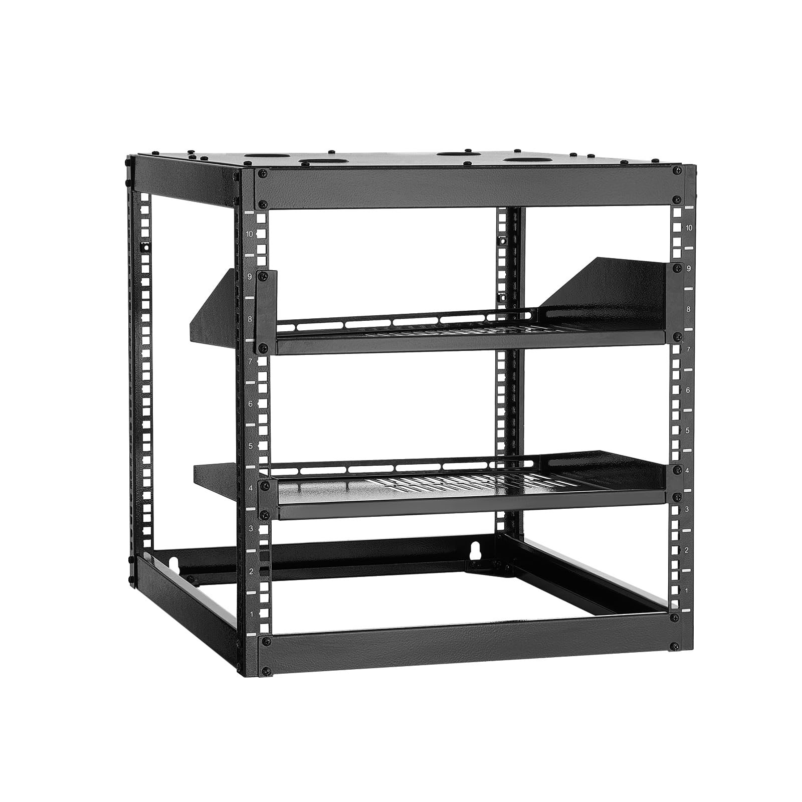
Figure 1: Fully assembled VEVOR 10U Server Rack.
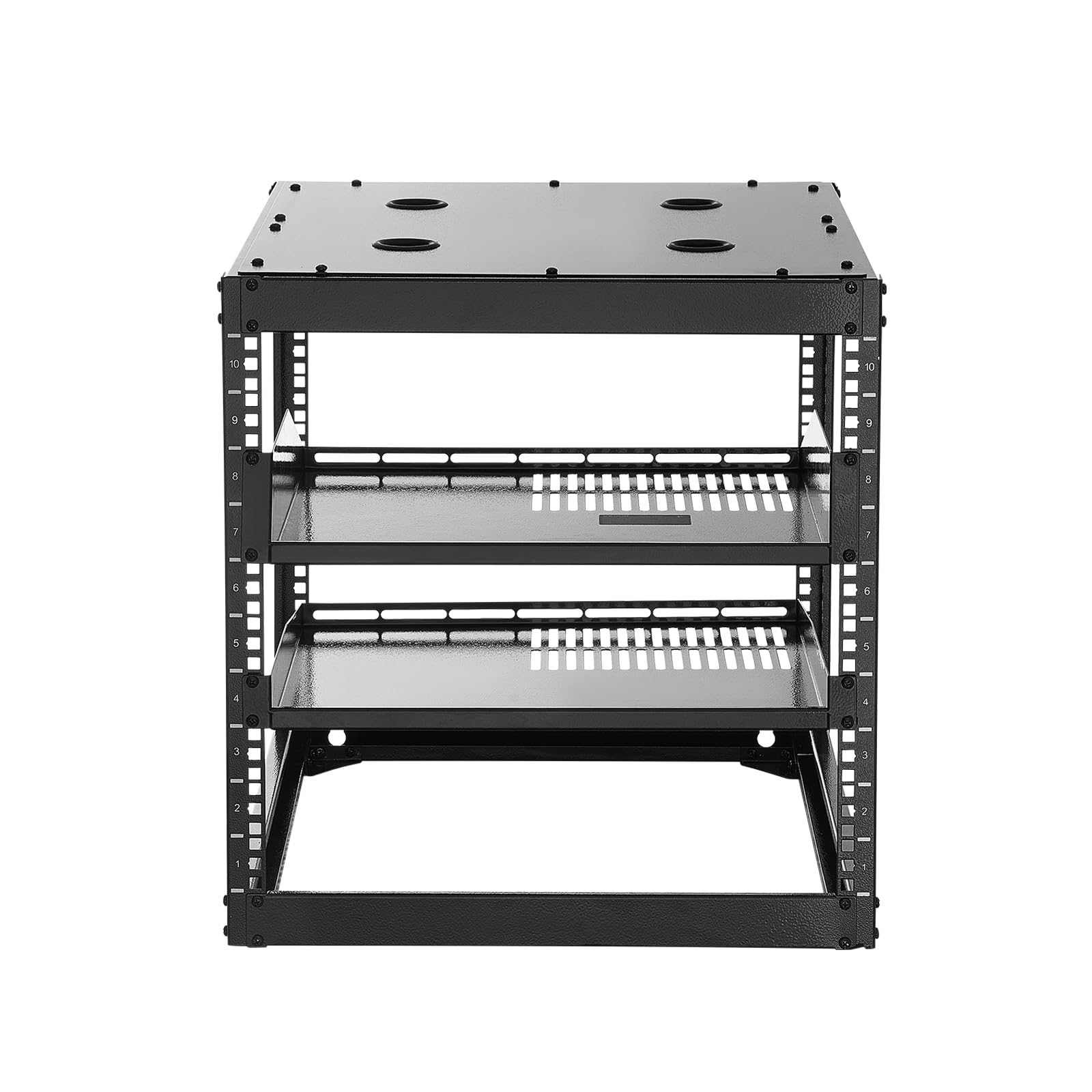
Figure 2: Detail of the rack's construction, highlighting material thickness and vertical posts.
Step 3: Install Shelves
Insert the cage nuts into the square holes on the vertical posts at your desired height. Align the shelves with the cage nuts and secure them using the provided screws. The shelves are vented to promote airflow.
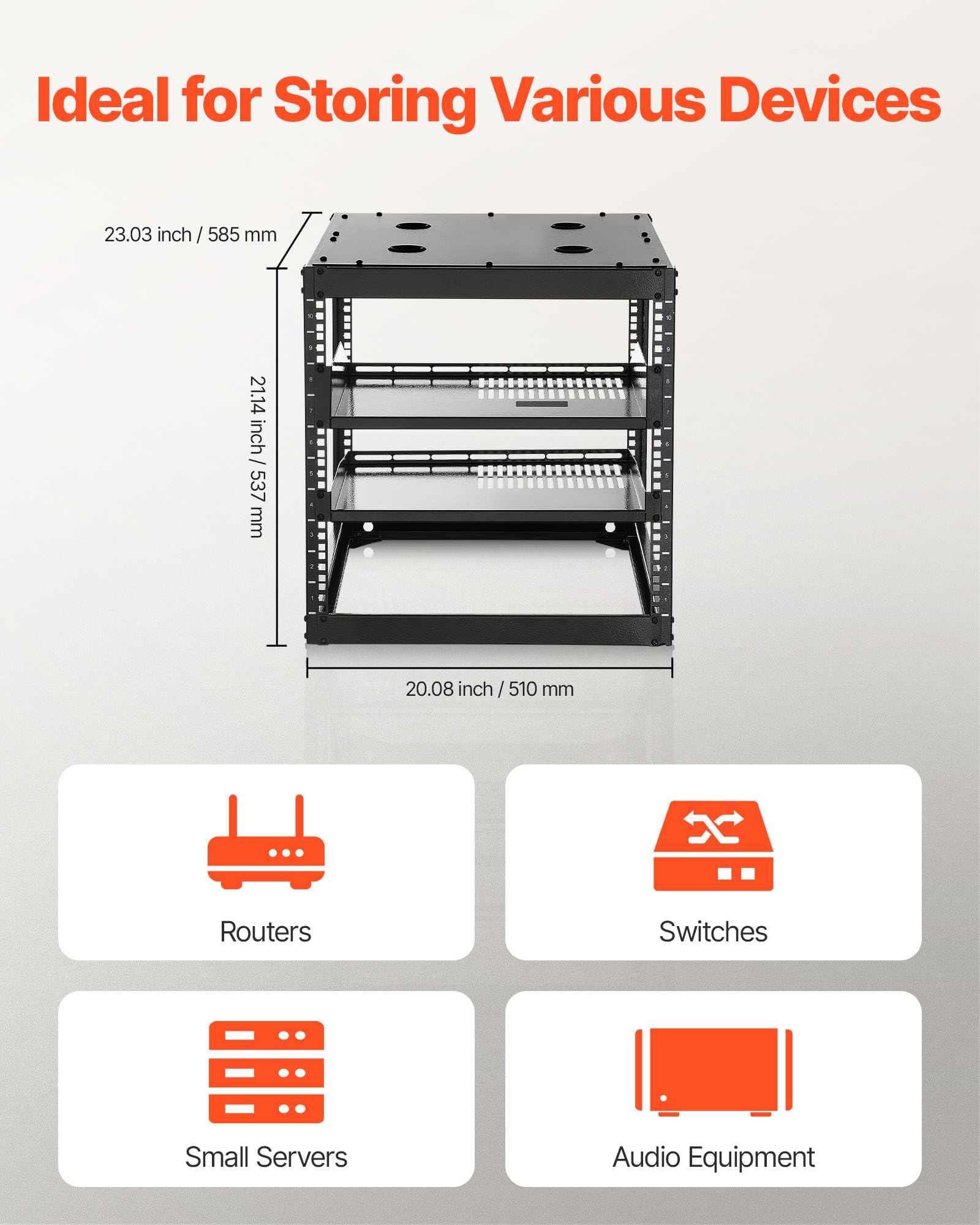
Figure 3: Vented shelves installed within the rack frame.
Step 4: Grounding
Attach the grounding wire to the designated grounding point on the rack. Ensure it is securely fastened to provide proper electrical grounding for your equipment.
Step 5: Floor-Standing Installation
Place the assembled rack in its desired location. Ensure the surface is level and stable. The rack is designed to support up to 500 lbs (226.8 kg) in this configuration.
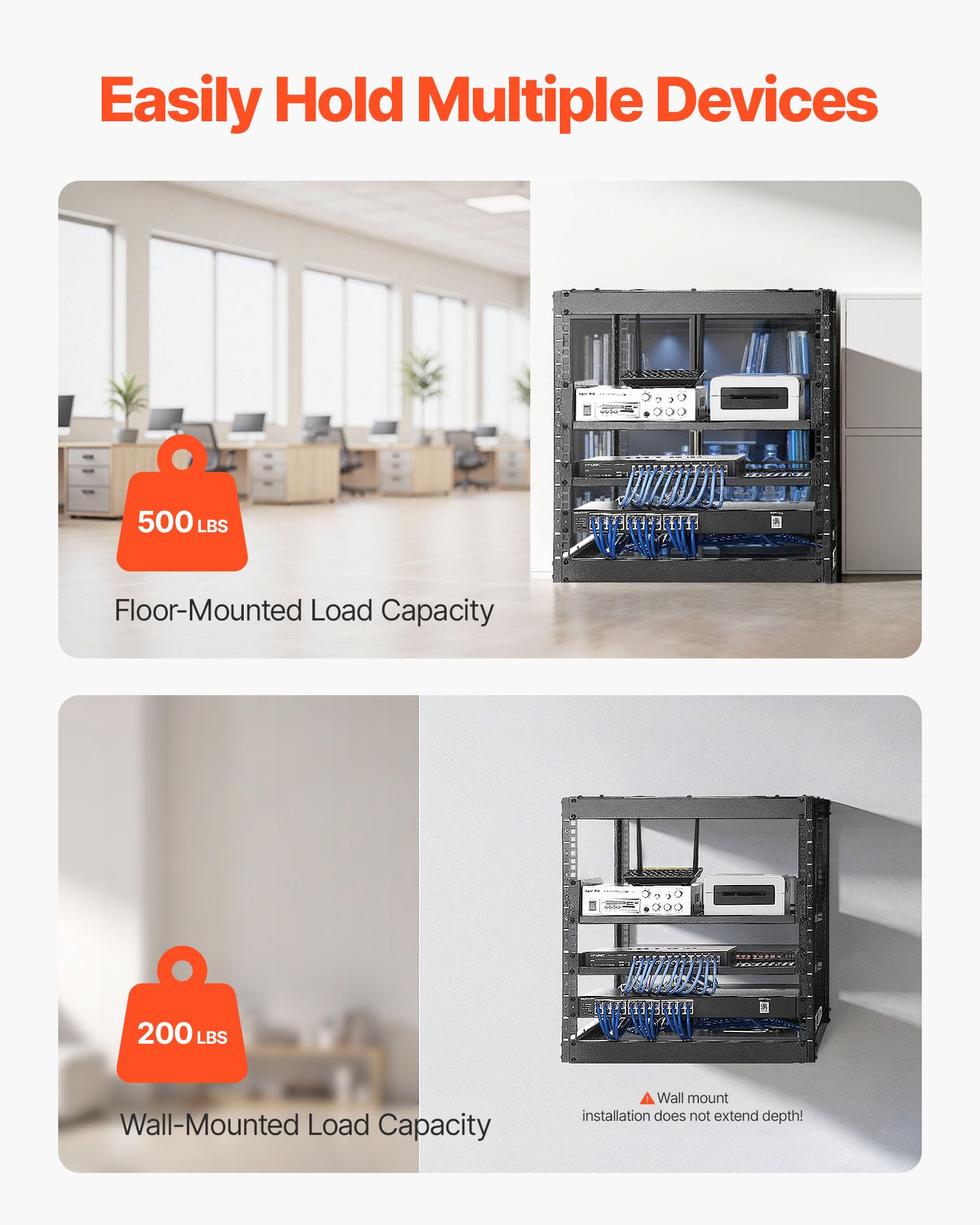
Figure 4: Rack in a floor-standing setup with equipment.
Step 6: Wall-Mounted Installation (Optional)
If wall-mounting, identify suitable structural studs or use appropriate wall anchors. Mark the drilling points using the rack's wall mount holes as a template. Drill pilot holes and securely fasten the rack to the wall using suitable hardware (not included). The wall-mounted capacity is 200 lbs (90.7 kg). Ensure the rack is level and securely attached before installing any equipment.
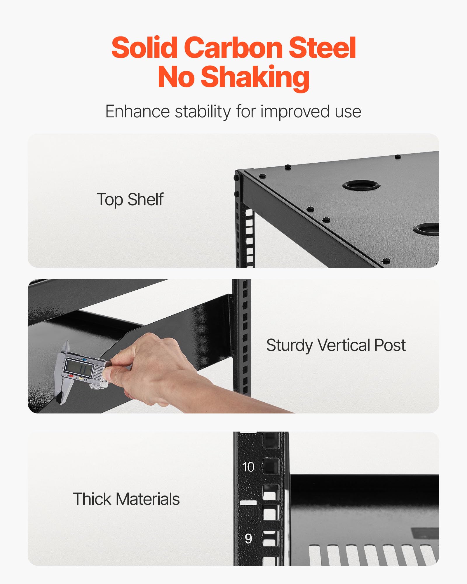
Figure 5: Rack installed in a wall-mounted configuration.
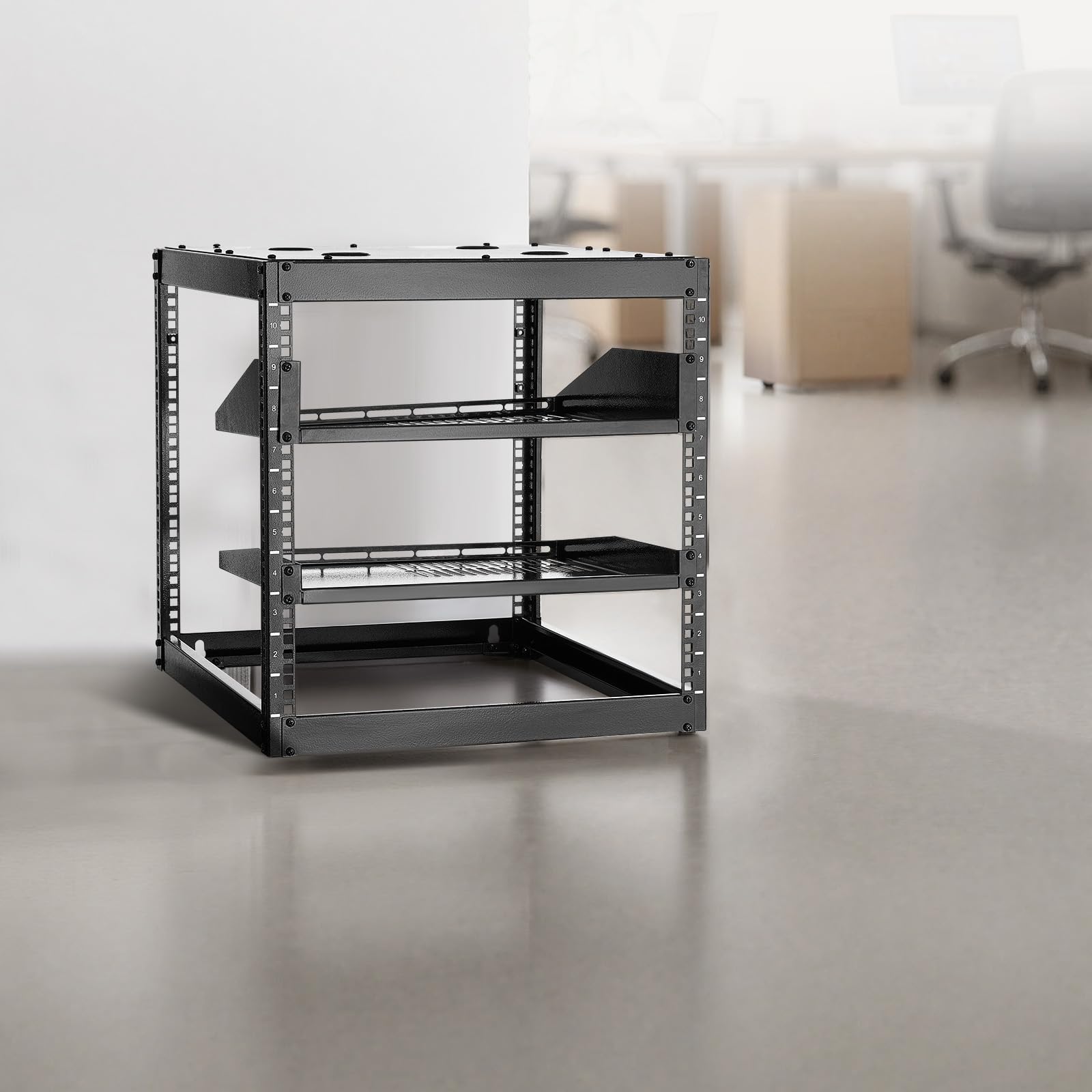
Figure 6: Close-up of the wall mount holes for installation.
Operating Instructions
Mounting Equipment
To mount 19-inch rack-mountable equipment, insert cage nuts into the square holes on the vertical posts at the desired U-height. Align your equipment's mounting ears with the cage nuts and secure using the appropriate rack screws (typically M6 or 10-32, included in the screw set). Ensure equipment is evenly distributed to maintain stability and balance.
Cable Management
The top panel features four grommet holes for routing cables. Utilize these holes to organize and manage network and power cables, preventing clutter and improving airflow within the rack.

Figure 7: Top panel with grommet holes for cable routing.
Load Capacity
Adhere strictly to the specified load capacities: 500 lbs (226.8 kg) for floor-standing installations and 200 lbs (90.7 kg) for wall-mounted installations. Distribute weight evenly across the rack to prevent stress on individual components.

Figure 8: Load capacity for floor-mounted and wall-mounted configurations.
Maintenance
Regular maintenance ensures the longevity and safe operation of your server rack.
- Cleaning: Periodically wipe down the rack with a soft, dry cloth to remove dust and debris. Avoid abrasive cleaners or solvents.
- Fastener Check: Annually inspect all screws and bolts to ensure they remain tight. Retighten as necessary.
- Load Inspection: Regularly verify that the total weight of installed equipment does not exceed the rack's specified capacity.
Troubleshooting
Common Issues and Solutions
| Issue | Possible Cause | Solution |
|---|---|---|
| Difficulty aligning screw holes during assembly. | Parts are not perfectly aligned or self-tapping screws require more force. | Ensure all parts are correctly oriented before tightening. Apply firm, steady pressure when driving self-tapping screws. A power drill with an appropriate bit is recommended. Do not fully tighten all screws until the frame is completely assembled. |
| Rack instability or wobbling. | Loose fasteners or uneven placement. | Verify all screws and bolts are securely tightened. For floor-standing, ensure the rack is on a level surface. For wall-mounted, confirm secure attachment to structural studs or appropriate anchors. |
| Exceeding weight capacity. | Too much equipment installed or uneven weight distribution. | Remove excess equipment to stay within the specified load limits (500 lbs floor-standing, 200 lbs wall-mounted). Redistribute equipment to ensure even weight distribution. |
Specifications
| Feature | Specification |
|---|---|
| Brand | VEVOR |
| Model Number | SPT-504-10A |
| Rack Height | 10U |
| Depth | 23.03 inches (585 mm) |
| Width | 20.08 inches (510 mm) |
| Height | 21.14 inches (537 mm) |
| Standard Mounting Width | 19 inches (482 mm) |
| Material | Q235 Carbon Steel |
| Floor-Mounted Load Capacity | 500 lbs (226.8 kg) |
| Wall-Mounted Load Capacity | 200 lbs (90.7 kg) |
| Net Weight | 28.7 lbs (13 kg) |
| Color | Black |
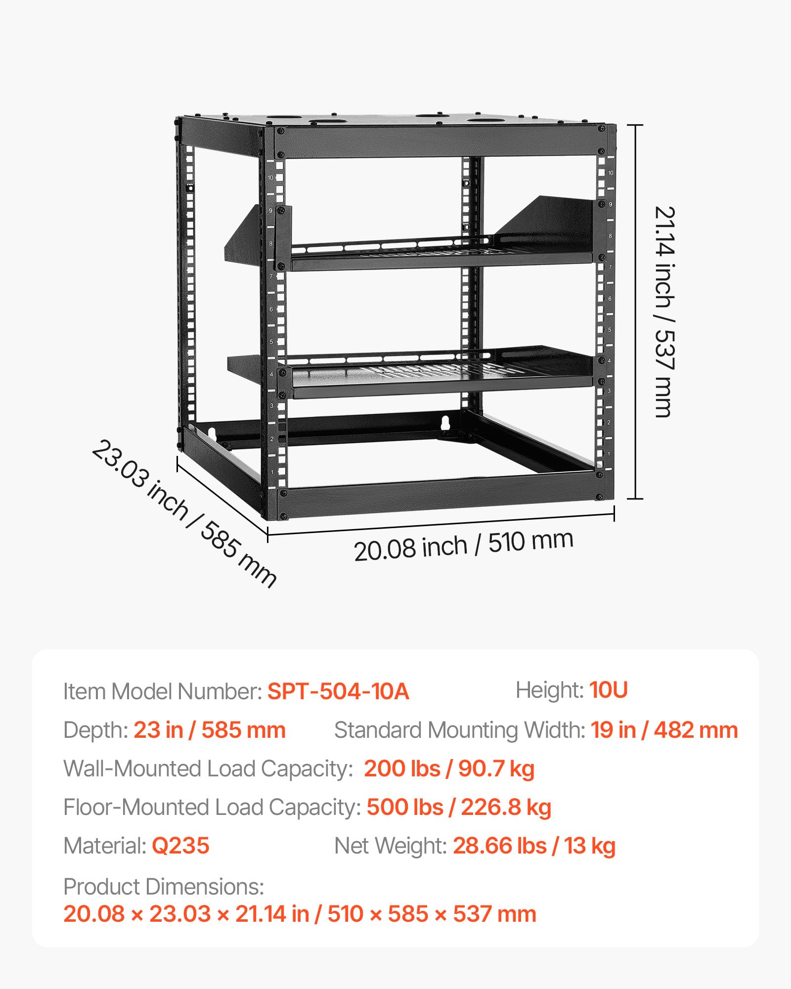
Figure 9: Detailed dimensions of the VEVOR 10U Server Rack.

Figure 10: Summary of key product specifications.
Warranty Information
This VEVOR 10U Open Frame Server Rack is covered by a standard manufacturer's warranty. For detailed information regarding warranty terms, conditions, and duration, please refer to the official VEVOR website or contact their customer service department directly. Keep your purchase receipt as proof of purchase for any warranty claims.
Customer Support
Should you require technical assistance, have questions about assembly or operation, or need to order replacement parts, please contact VEVOR customer support. You can typically find contact information, FAQs, and additional resources on the official VEVOR website.
Website: www.vevor.com


