1. Introduction
The WOYO CTB007 PRO is a professional diagnostic tool designed for automotive technicians and enthusiasts. It functions as an OBD2 breakout box, CAN tester, and ECU testing tool, supporting both 12V and 24V vehicle systems. This manual provides detailed instructions for its setup, operation, and maintenance to ensure safe and effective use.
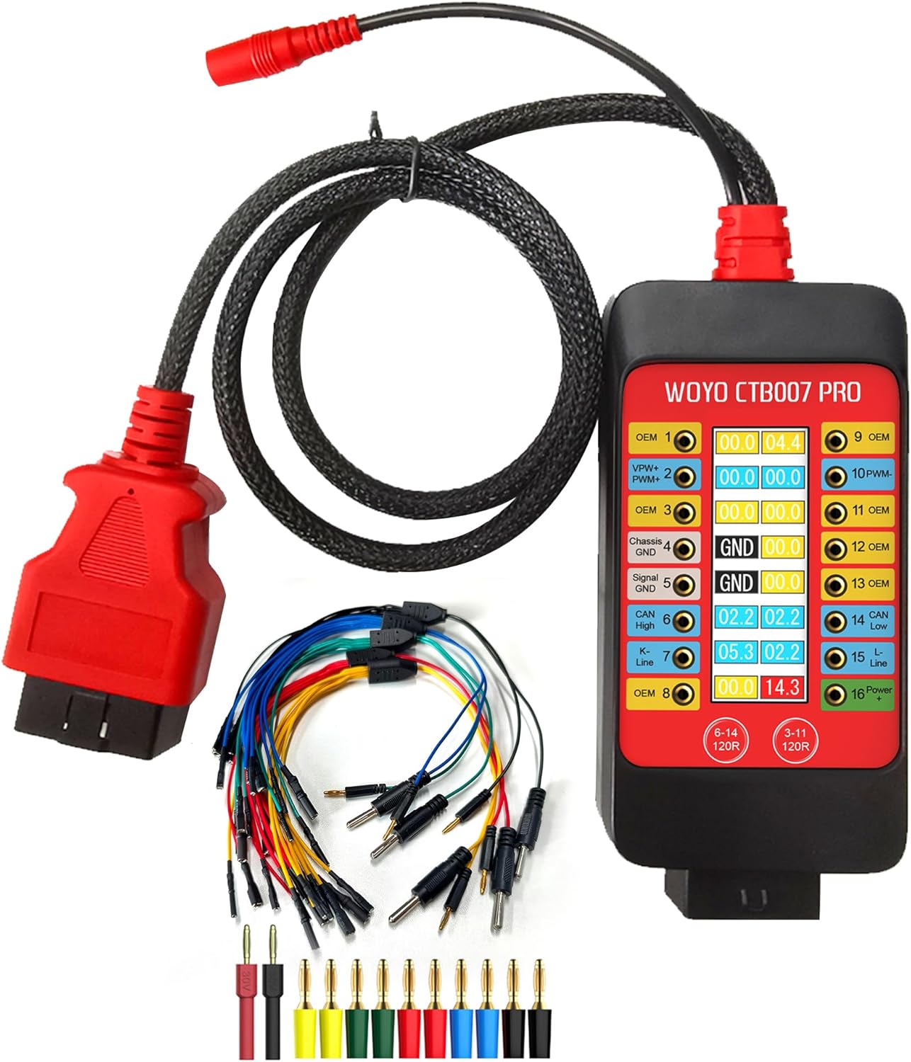
Figure 1: WOYO CTB007 PRO OBD2 Breakout Box and included accessories.
2. Product Overview
2.1 Key Features
- Universal Compatibility: Supports 12V-24V OBD systems for passenger cars and commercial vehicles.
- Real-time OBD-II Pin Voltage Monitoring: Features a digital LCD display showing true RMS voltage (Vrms) for all 16 OBD-II pins.
- Visual Indicators: Green background for dynamic signals and status alerts for PIN 4&5 ground (GND) connectivity.
- Built-in 120Ω Resistance Switches: For HS-CAN (PIN6&14) and OEM/MS-CAN (PIN3&11) to improve signal integrity during bench testing.
- Voltage Protection: Audible alarms for high and low voltage conditions on PIN16 (12V and 24V systems) and reverse polarity protection. Maximum load current is 2.0A.
- ECU Testing Capability: Provides convenient connectivity for IGN/START activation or external wake-up tools for bench testing ECUs.
- Battery Replacement Memory Saver: Maintains vehicle power during battery changes to preserve vehicle settings.
- Durable Extension Cable: Includes a 27.5-inch/59-inch OBD2 extension cable made of robust PET braided tube material.
2.2 Package Contents
- WOYO CTB007 PRO Main Device
- Portable Bag
- 5x ECU Breakout Leads
- Banana Pin Connectors
3. Setup
Before using the WOYO CTB007 PRO, ensure all connections are secure and correct.
- Connect to Vehicle: Plug the OBD2 connector of the CTB007 PRO into the vehicle's OBD2 port. The device will power on automatically.
- External Power (Optional): For extended bench testing or specific scenarios, connect an external 9-32V DC power supply (DC 12V 5.5*2.1mm) to the designated input port on the device.
- Connect Diagnostic Tools: Connect your diagnostic scanner, oscilloscope, or multimeter to the appropriate banana pin sockets on the CTB007 PRO for signal monitoring or ECU communication.
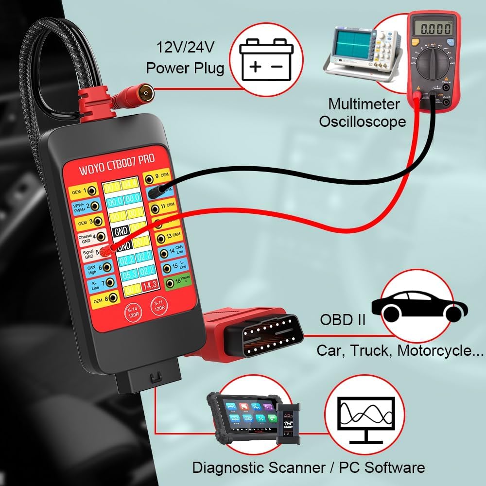
Figure 2: Typical setup for vehicle diagnostics using the CTB007 PRO.
4. Operating Instructions
4.1 Real-time OBD-II Pin Voltage Monitoring
The integrated LCD display shows the real-time Vrms (Root Mean Square voltage) of all 16 OBD-II pins. This allows for quick identification of active signals and power supply status.
- Signal Detection: If the device detects a pulse or waveform signal on a pin, the corresponding number background color will flash green.
- Ground (GND) Detection: The display will show "GND" for pins 4 (Chassis Ground) and 5 (Signal Ground) if they are properly connected. If not normal, it will display "OPEN".

Figure 3: Digital LCD Display showing PIN Vrms and ground detection.
4.2 120Ω CAN Termination Switches
The CTB007 PRO includes built-in 120Ω resistor switches for CAN bus lines. These resistors are crucial for compensating for missing termination in single-ECU or small bench networks, which helps improve signal integrity and reduce reflections.
- HS-CAN: Activate the 120Ω resistor for pins 6 and 14 (standard CAN High and CAN Low).
- OEM/MS-CAN: Activate the 120Ω resistor for pins 3 and 11 (vehicle-dependent).
Press the corresponding button (6-14 120R or 3-11 120R) on the device to toggle the 120Ω resistance on or off.

Figure 4: 120Ω CAN Termination Switches.
4.3 ECU Testing on Bench
The CTB007 PRO facilitates convenient ECU testing outside of the vehicle. It provides necessary connections for IGN/START activation or external wake-up tools, allowing ECUs to be powered and exercised on a workbench.
- Connect the CTB007 PRO to a 9-32V power supply.
- Use the provided ECU breakout leads to connect the ECU to the CTB007 PRO.
- Connect your scanner or code reader programmer to the CTB007 PRO to communicate with the ECU.

Figure 5: Bench testing an ECU with the CTB007 PRO.
4.4 Battery Replacement Memory Saver
The CTB007 PRO can be used to maintain vehicle power during battery changes, preventing the loss of vehicle settings such as radio presets, clock, and ECU learned values.
- Ensure the car is closed and the ignition key is off.
- Connect the CTB007 PRO to a 12V/24V power supply (either external DC 12V 5.5*2.1mm or a separate 12V/24V battery connected to PIN 5 & PIN 16).
- Connect the CTB007 PRO to the vehicle's OBDII plug. This will power the car's systems, saving ECU data.
- Proceed to safely remove and replace the old battery with a new one.

Figure 6: Battery replacement procedure using CTB007 PRO.
4.5 Voltage Protection and Alarms
The device provides audible alarms for voltage conditions on PIN 16 (Battery positive +) to alert the user of potential issues:
- Low-voltage Alarm (slow beep):
- 12V systems: < 11.8 V
- 24V systems: < 23.6 V
- High-voltage Alarm (fast beep):
- 12V systems: > 15.5 V
- 24V systems: > 31 V
The CTB007 PRO also features reverse polarity protection to prevent damage from incorrect power connections.
4.6 16-Pin Definition
Understanding the OBD-II 16-pin definitions is essential for proper diagnosis and connection of external tools.

Figure 7: OBD-II 16-Pin Definition.
5. Specifications

Figure 8: WOYO CTB007 PRO Specifications.
| Feature | Specification |
|---|---|
| Input Voltage | 9.0-32.0VDC |
| Maximum Load | 2.0A |
| Resolution | 0.1V |
| Probes Socket | 16P*2.0mm |
| Overload Protection | Yes, PTC Fuse (Self-Healing) |
| Reverse Polarity Protection | Yes |
| Protocol Standard | PWM(J1850), VPW(J1850), ISO 9141-2, DIS/ISO 14230-4, CAN(J-2284) |
| Operating Temperature | -20°C-85°C, Humidity <70% |
| OBD Cable Length | 70cm (27.5inch) / 150cm (59inch) |
| Item Weight | 1.54 pounds |
| Product Dimensions | 5.9 x 2.7 x 0.98 inches |
6. Maintenance
- Cleaning: Use a soft, dry cloth to clean the device. Avoid using abrasive cleaners or solvents.
- Storage: Store the CTB007 PRO in its portable bag in a cool, dry place away from direct sunlight and extreme temperatures.
- Cable Care: Avoid sharp bends or kinks in the OBD2 extension cable to prevent internal wire damage.
- Inspection: Periodically inspect the device and cables for any signs of damage or wear. Do not use if damaged.
7. Troubleshooting
- Device Not Powering On: Ensure the OBD2 connector is securely plugged into the vehicle's port. Verify the vehicle's battery has sufficient charge. If using external power, check the power supply connection and voltage.
- No Signal Readings: Confirm the vehicle's ignition is on (if required for communication). Check all connections to diagnostic tools. Ensure the correct pins are selected for monitoring.
- Incorrect Voltage Readings: Verify the device is correctly set for 12V or 24V systems if applicable (though the CTB007 PRO automatically detects). Ensure good contact with the pins.
- CAN Communication Issues: If experiencing problems with CAN bus communication, ensure the 120Ω termination switches are correctly set for your specific application (on or off as needed).
- Audible Alarms: If an alarm sounds, check the voltage on PIN 16 as indicated on the display. Address any low or high voltage conditions in the vehicle's electrical system.
8. Warranty and Support
For warranty information, technical support, or service inquiries, please refer to the contact information provided with your purchase or visit the official WOYO website. Keep your purchase receipt as proof of purchase.


