1. Introduction
Thank you for purchasing the zmart DIY LED Digital Calculator Kit. This kit is designed to provide an engaging electronic assembly experience, allowing users to build a functional LED digital calculator. It is an excellent tool for soldering practice and electronic learning, featuring a single-chip microcomputer and a clear digital tube display. This manual provides comprehensive instructions for assembly, operation, and maintenance.
2. Product Overview
The zmart DIY LED Digital Calculator Kit combines practical electronic assembly with a fully functional calculator. Key features include:
- LED Digital Tube Display: Provides clear numerical output.
- Single-Chip Microcomputer: Powers the calculator's logic and functions.
- Dual Power Options: Supports both Type-C USB and CR2032 coin cell battery for flexible power supply.
- Soldering Practice: Ideal for developing and refining soldering skills.
- Color Ring Resistance Conversion: A dedicated function for electronic enthusiasts.
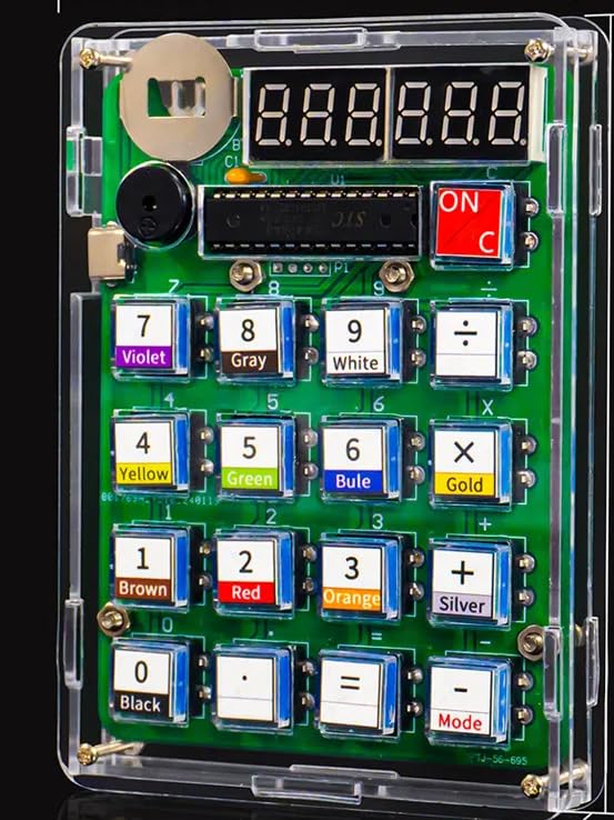
Image 2.1: Assembled DIY Calculator Kit. This image highlights the kit's features, including color coding, calculation capabilities, Type-C/battery dual power, a 6-bit display, and integrated buzzer/speaker.

Image 2.2: Function Diagram. This diagram illustrates the various components and their functions, including the 5V Type-C power interface, coin cell battery slot, 6-digit digital tube display, buzzer, work/rest mode switch, and buttons for mathematical calculations and color ring resistance conversion.
3. Components List
Before beginning assembly, verify that all components listed below are present in your kit. Refer to the image for visual identification.

Image 3.1: DIY Parts. This image displays all the individual components included in the kit, such as the PCB, LED display, buttons, resistors, capacitors, integrated circuits, battery holder, and transparent casing parts.
- Main Printed Circuit Board (PCB)
- LED Digital Tube Display module
- Microcontroller chip
- Tactile buttons (various colors/functions)
- Resistors (for color ring conversion practice)
- Capacitors
- Diodes
- Buzzer/Speaker component
- CR2032 Coin Cell Battery Holder
- Transparent protective shell components
- Screws and fasteners
- CR2032 Battery (included)
4. Setup and Assembly
This kit requires soldering. Ensure you have appropriate soldering equipment (soldering iron, solder, desoldering wick/pump, safety glasses) and a well-ventilated workspace.
4.1 Soldering Components to the PCB
Follow the circuit diagram and component placement markings on the PCB to solder each component. Pay close attention to component polarity (for diodes, LEDs, and integrated circuits) and orientation.

Image 4.1: Circuit Diagram. This diagram provides the electrical schematic for the calculator, essential for correct component placement and soldering.
- Start with smaller components like resistors and diodes, then move to larger ones like integrated circuits and button switches.
- Ensure all solder joints are clean, shiny, and form a good connection without bridging.
- Solder the LED digital tube display module to its designated header pins.
- Solder the buzzer/speaker component.
- Solder the Type-C USB power interface and the CR2032 battery holder.
4.2 Assembling the Protective Shell
Once all electronic components are soldered and tested (if possible), proceed with assembling the transparent protective shell.
- Carefully place the assembled PCB into the bottom half of the transparent shell.
- Insert the individual button caps into their respective slots on the top half of the shell.
- Align the top and bottom shell halves, ensuring all components fit correctly.
- Secure the shell halves using the provided screws. Do not overtighten.
4.3 Battery Installation
The kit includes one CR2032 coin cell battery. Install it into the battery holder on the PCB, ensuring correct polarity (positive side up, typically marked with a '+' symbol).
5. Operating Instructions
The calculator can be powered via the installed CR2032 battery or by connecting a Type-C USB cable (not included) to the Type-C port.
5.1 Powering On/Off
- To power on, slide the 'ON/C' switch to the 'ON' position. The LED display will illuminate.
- To power off, slide the 'ON/C' switch to the 'OFF' position.
5.2 Basic Calculator Functions
Use the numerical buttons (0-9) to input numbers and the operation buttons (+, -, ×, ÷) for calculations. Press '=' to display the result.
- 'ON/C' button: Clears the current entry or calculation.
- '+', '-', '×', '÷' buttons: Perform addition, subtraction, multiplication, and division respectively.
- '=' button: Executes the calculation and displays the result.
- '.' button: Enters a decimal point.
5.3 Mode Button and Color Ring Resistance Conversion
The 'Mode' button allows switching between different functionalities, including the color ring resistance conversion mode.

Image 5.1: Color Ring Resistance Conversion. This image shows how the calculator can be used to identify resistor values by inputting the color codes. The transparent keys are also visible.
- Press the 'Mode' button to cycle through available modes.
- In the color ring resistance conversion mode, input the numerical values corresponding to the color bands of a resistor.
- The calculator will automatically identify whether it's a 4-band or 5-band resistor and display its resistance value.
- A long press on certain buttons may activate additional functions related to resistance value conversion, as indicated in the function diagram.
6. Maintenance
Proper maintenance ensures the longevity and optimal performance of your DIY calculator.
- Cleaning: Use a soft, dry cloth to clean the exterior of the calculator. Avoid using abrasive cleaners or solvents, as they may damage the transparent shell or electronic components.
- Battery Replacement: When the display dims or the calculator functions erratically, it may be time to replace the CR2032 battery. Ensure the calculator is powered off before replacing the battery. Dispose of old batteries responsibly.
- Storage: Store the calculator in a cool, dry place away from direct sunlight and extreme temperatures.
7. Troubleshooting
If you encounter issues with your zmart DIY LED Digital Calculator Kit, refer to the following troubleshooting guide:
| Problem | Possible Cause | Solution |
|---|---|---|
| Calculator does not power on. | Battery is dead or incorrectly installed. Power switch is off. Loose connection. | Check battery polarity and replace if necessary. Ensure 'ON/C' switch is in 'ON' position. Inspect soldered connections for continuity. |
| Incorrect calculation results. | Incorrect button input. Faulty component or solder joint. | Double-check input values. Re-examine circuit diagram and component soldering for errors. |
| Display is dim or flickering. | Low battery. Poor connection to display module. | Replace CR2032 battery. Check soldering of the LED display module. |
| Buttons are unresponsive. | Button not properly seated. Faulty button switch. | Ensure button caps are correctly aligned. Check soldering of the button switches. |
If the problem persists after attempting these solutions, please contact zmart customer support for further assistance.
8. Specifications
The following are the technical specifications for the zmart DIY LED Digital Calculator Kit:

Image 8.1: Product Size. This image illustrates the physical dimensions of the assembled calculator, measuring 85mm (3.34 inches) in width, 119mm (4.68 inches) in length, and 16mm (0.62 inches) in thickness.
- Model Name: DIY Calculator
- Brand: zmart
- Display Type: LED Digital Tube
- Calculator Type: General Calculator
- Power Source: CR2032 Coin Cell Battery (1, included) or Type-C USB (cable not included)
- Color: Transparent (shell)
- Package Dimensions: 18.3 x 15.3 x 4.5 cm (7.2 x 6.0 x 1.8 inches)
- Product Weight: 110 g (0.24 lbs)
- ASIN: B0FMXW1CSM
9. Warranty and Support
For warranty information or technical support regarding your zmart DIY LED Digital Calculator Kit, please refer to the seller's policies on the platform where the product was purchased. Typically, support can be accessed through your order history or by contacting the seller directly.
Keep your proof of purchase for any warranty claims.


