1. Introduction and Overview
This manual provides detailed instructions for the installation, operation, and maintenance of your MACHINIST B450 Motherboard. The MACHINIST B450 Motherboard is designed to support AMD AM4 socket Ryzen 1st through 5th generation processors, offering a robust platform for personal computing.
Key features include dual-channel DDR4 memory support, NVME/NGFF M.2 storage, SATA 3.0, PCIe 3.0 expansion slots, USB 3.0 connectivity, Gigabit LAN, and integrated VGA and HDMI-Compatible video outputs (requires a CPU with integrated graphics).

Image 1.1: The MACHINIST B450 Motherboard alongside its product packaging.
2. Setup and Installation
2.1. CPU Installation (AMD AM4 Socket)
The motherboard features an AMD AM4 socket, compatible with AMD Ryzen 1st, 2nd, 3rd, 4th, and 5th generation processors. Examples include Ryzen 9 5900XT, Ryzen 7 5800X, Ryzen 3 5305G, Ryzen 5 3600X, Ryzen 7 2700X, and Ryzen 7 1800X.
- Carefully lift the CPU socket lever.
- Align the triangular mark on your AMD Ryzen CPU with the corresponding mark on the AM4 socket.
- Gently place the CPU into the socket without forcing it.
- Lower the CPU socket lever to secure the processor in place.
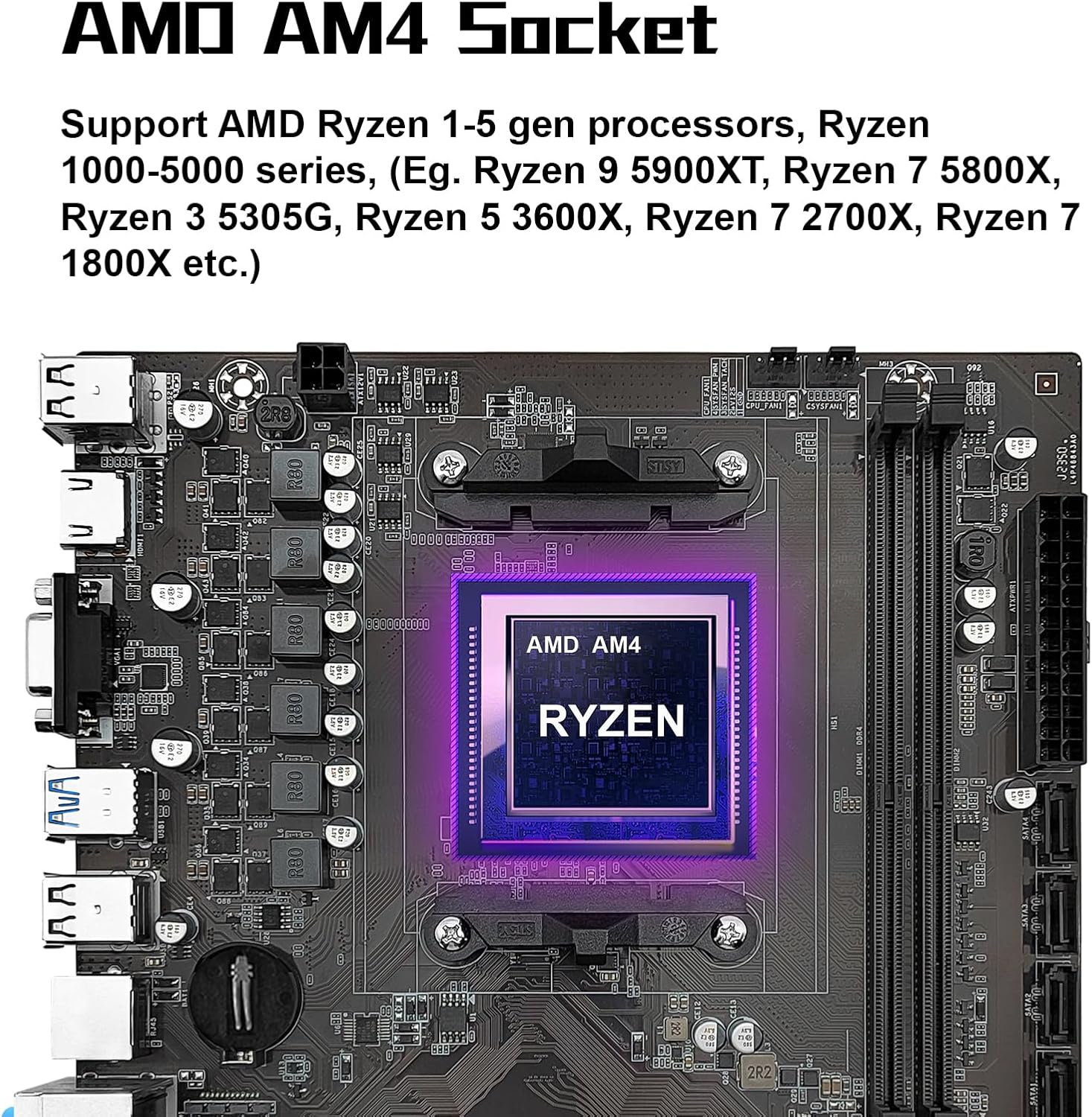
Image 2.1: Close-up view of the AMD AM4 CPU socket on the motherboard, highlighting its design for Ryzen processors.
2.2. Memory Installation (DDR4)
The motherboard supports dual-channel DDR4 non-ECC desktop memory. It features two DDR4 memory slots, supporting a maximum capacity of 64GB (32GB per slot). Supported effective frequencies include 2133MHz, 2400MHz, 2666MHz, 2800MHz, 3000MHz, 3200MHz, and 3600MHz.
- Open the clips at both ends of the DDR4 memory slots.
- Align the notch on the DDR4 memory module with the key in the memory slot.
- Insert the memory module firmly into the slot until the clips snap into place.
- Ensure both clips are fully closed and the module is seated correctly.

Image 2.2: The dual-channel DDR4 memory slots on the MACHINIST B450 Motherboard, indicating their position and design.
2.3. Storage Device Installation
2.3.1. NVME/NGFF M.2 Slot
The motherboard includes one M.2 slot that supports both NVME and NGFF hard disks. This slot utilizes PCIe 3.0 x4 bandwidth, allowing for transfer speeds up to 3600MB/s.
- Locate the M.2 slot on the motherboard.
- Remove the M.2 standoff screw.
- Insert the M.2 SSD into the slot at an angle.
- Gently push down the M.2 SSD and secure it with the standoff screw.

Image 2.3: The NVME M.2 slot on the motherboard, illustrating its location and compatibility with high-speed storage.
2.3.2. SATA 3.0 Ports
The motherboard is equipped with SATA 3.0 interfaces for connecting traditional hard drives and SSDs. These ports offer a maximum read and write speed of 6Gb/s.
- Connect one end of a SATA data cable to a SATA 3.0 port on the motherboard.
- Connect the other end of the SATA data cable to your SATA storage device (HDD/SSD).
- Connect a SATA power cable from your power supply unit (PSU) to the SATA storage device.

Image 2.4: A visual representation of the SATA 3.0 interfaces on the motherboard, indicating their placement.
2.4. Expansion Card Installation (PCIe)
The motherboard provides one PCIe 3.0 x16 slot and one PCIe 2.0 x1 slot for expansion cards. The PCIe 3.0 x16 slot supports data transfer speeds up to 32GB/s.
- Align your expansion card (e.g., graphics card) with the desired PCIe slot.
- Press down firmly until the card is fully seated in the slot.
- Secure the card to your PC case with a screw.
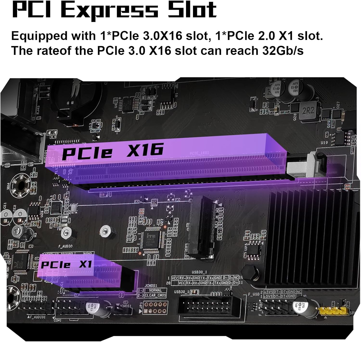
Image 2.5: The PCIe 3.0 x16 and PCIe 2.0 x1 slots on the motherboard, used for graphics cards and other expansion devices.
2.5. Power Connections
Connect the 24-pin ATX power connector and the 4-pin CPU power connector from your power supply unit (PSU) to the corresponding ports on the motherboard. Ensure all power connections are secure.
2.6. Front Panel and I/O Connections
Connect the front panel headers (power switch, reset switch, HDD LED, power LED) to their respective pins on the motherboard. Connect USB 2.0, USB 3.0, and audio headers from your case to the motherboard. The rear I/O panel includes HDMI-Compatible, VGA, USB 3.0, USB 2.0, RJ45 (Gigabit LAN), and audio ports.
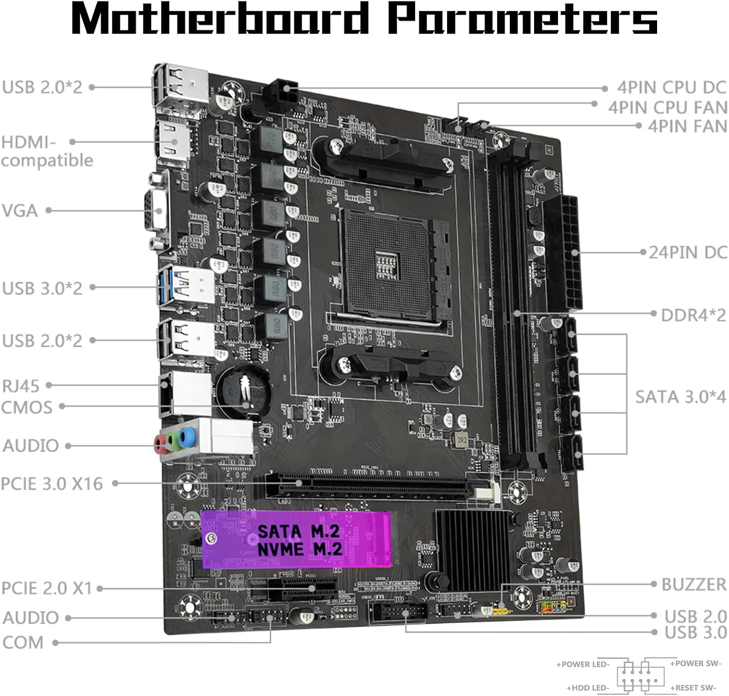
Image 2.6: A detailed diagram of the MACHINIST B450 Motherboard, labeling various ports and connectors for easy identification during setup.

Image 2.7: The VGA and HDMI-Compatible output ports on the motherboard, which support 1080P high-definition video output. Note that a CPU with integrated graphics is required to utilize these outputs.
3. Operating Instructions
3.1. Initial Boot and BIOS/UEFI Configuration
After assembling your system, power it on. During startup, press the designated key (usually DEL or F2) to enter the BIOS/UEFI setup. Here you can configure boot order, system time, and other hardware settings.
3.2. Driver Installation
For optimal performance, it is essential to install the necessary drivers for your motherboard components. While a user manual is not included in the package, drivers can typically be downloaded from the manufacturer's official website. Alternatively, tools like Driver Talent or using a Windows 10 operating system (which often includes many generic drivers) can assist with driver installation.
4. Maintenance
4.1. Clearing CMOS
Clearing the CMOS (Complementary Metal-Oxide-Semiconductor) can resolve various system issues, such as incorrect BIOS settings or boot problems. You do not need to remove the CMOS battery for this method, but the motherboard must be disconnected from power.
- Disconnect the power supply from the motherboard.
- Locate the CMOS clear jumper (often labeled CLR_CMOS or similar) on the motherboard, typically near the bottom right corner.
- Remove the jumper cap from its default position (usually pins 1 and 2).
- Place the jumper cap onto pins 2 and 3 for approximately 5 seconds.
- Return the jumper cap to its original position (pins 1 and 2).
- Reconnect the power supply and power on the system.

Image 4.1: Visual guide for the CMOS clear method, showing the jumper cap's positions for resetting.
5. Troubleshooting
5.1. System Does Not Power On / Fans Do Not Spin
If your system fails to power on and the fans remain inactive, consider the following steps:
- Verify that both the motherboard's 24-pin power connector and the CPU's 4-pin power connector are securely connected from the power supply.
- Confirm the compatibility and condition of your CPU and memory modules.
- Ensure that all memory modules are properly seated in their slots.
- If the issue persists after these checks, attempt to clear the CMOS as described in Section 4.1.
5.2. No Display Output (Fans Spin, Keyboard Lights Unresponsive)
If the system powers on and fans spin, but there is no display and keyboard lights (e.g., Caps Lock) do not respond, perform these checks:
- Re-verify the motherboard and CPU power connections.
- Ensure all memory modules are correctly seated.
- Confirm CPU and memory model compatibility and condition.
- If problems continue, clear the CMOS (Section 4.1).
5.3. No Display Output (Fans Spin, Keyboard Lights Responsive)
If the system powers on, fans spin, and keyboard lights respond (e.g., Caps Lock indicator lights up), but there is still no display, follow these troubleshooting steps:
- Verify that your monitor is powered on and the display data cable (HDMI or VGA) is securely connected to the correct output port.
- If no external graphics card (GPU) is installed, confirm that your CPU supports integrated graphics.
- If an external graphics card (GPU) is installed, ensure the display data cable is connected to the graphics card's output port, not the motherboard's integrated ports.
- Check the condition of the display cable, GPU, and monitor for any damage or malfunction.
- If the issue persists after these checks, clear the CMOS (Section 4.1).
6. Specifications
| Feature | Specification |
|---|---|
| Brand | MACHINIST |
| Model Name | B450 |
| CPU Socket | Socket AM4 |
| Compatible Processors | AMD AM4 socket Ryzen 1-5th gen Processors |
| Chipset Type | AMD B450 |
| RAM Memory Technology | DDR4 |
| Memory Slots | 2 (Dual-channel) |
| Maximum Memory Capacity | 64 GB (32GB*2) |
| Supported Memory Frequencies | 2133MHz/2400MHz/2666MHz/2800MHz/3000MHz/3200MHz/3600MHz |
| M.2 Slot | 1 (NVME/NGFF, PCIe 3.0 x4, up to 3600MB/s) |
| SATA Ports | 4 x SATA 3.0 (6Gb/s) |
| PCIe Expansion Slots | 1 x PCIe 3.0 x16, 1 x PCIe 2.0 x1 |
| Video Output | VGA, HDMI-Compatible (requires CPU with integrated graphics) |
| LAN | Gigabit Ethernet (Realtek8111H) |
| USB Ports | USB 3.0, USB 2.0 |
| Platform | Windows |
| Item Weight | 1.5 pounds |
| Package Dimensions | 10.8 x 8.8 x 2.2 inches |
7. Warranty and Support
For warranty information, technical support, and driver downloads, please refer to the official MACHINIST website or contact their customer service. The package includes the B450 motherboard, one SATA cable, and one I/O baffle. A CMOS battery is not included.


