1. Product Overview
The FNIRSI 2C53T is a versatile 3-in-1 handheld device combining the functionalities of a dual-channel digital oscilloscope, a 4.5-digit 19999-count multimeter, and a DDS signal generator. This compact instrument is designed for professionals, students, and hobbyists requiring a portable solution for electronic testing and waveform analysis.
Key Features:
- Dual-Channel Oscilloscope: 50 MHz analog bandwidth, 250 MSa/s real-time sampling rate, 1 Kpts record depth, automatic measurement functions, maximum input voltage of 400V, vertical sensitivity from 10 mV/div to 10 V/div. Supports waveform image storage and export.
- 4.5-Digit, 19999-Count Multimeter: Measures AC Voltage (0-750 V), DC Voltage (0-999.9 V), DC/AC Current (0-9.999 A), Resistance (0-19.99 MΩ), and Capacitance (0-99.99 mF). Includes continuity measurement.
- DDS Signal Generator: Generates 13 types of waveforms with a maximum output frequency of 50 kHz and a 1 Hz interval.
- Data Saving Function: One-click saving and screening of data. Connects to PC via Type-C for saved image upload. Allows comparison of reference and measured waveforms on the same screen.
- Robust Design: Features an FPGA+MCU+ADC hardware architecture, integrated high-voltage protection module, 2.8-inch LCD display, and a built-in 3000 mAh lithium-ion battery providing up to 6 hours of standby time. Type-C interface supports 5V/1A charging.

Image 1.1: The FNIRSI 2C53T device showcasing its 3-in-1 capabilities as an oscilloscope, multimeter, and signal generator.
2. Safety Information
Please read all safety information carefully before using the device to prevent electric shock, injury, or damage to the instrument. Keep this manual for future reference.
- Always use the correct input terminals, function, and range for measurements.
- Do not apply voltage or current that exceeds the maximum rated values specified for the device.
- Inspect test leads for damage before each use. Do not use if insulation is damaged or bare metal is exposed.
- Do not operate the device in wet environments or with wet hands.
- Ensure the device is turned off and disconnected from any circuits before changing functions or connecting/disconnecting test leads.
- Refer to the specifications section for maximum input ratings for each function.
- Do not attempt to repair or modify the device. Refer servicing to qualified personnel.
3. Product Components
The FNIRSI 2C53T package typically includes the following items:
- FNIRSI 2C53T 3-in-1 Device
- Oscilloscope Probes (x2)
- Multimeter Test Leads (Red and Black)
- Type-C USB Cable
- User Manual (this document)
- Carrying Case (may vary by package)
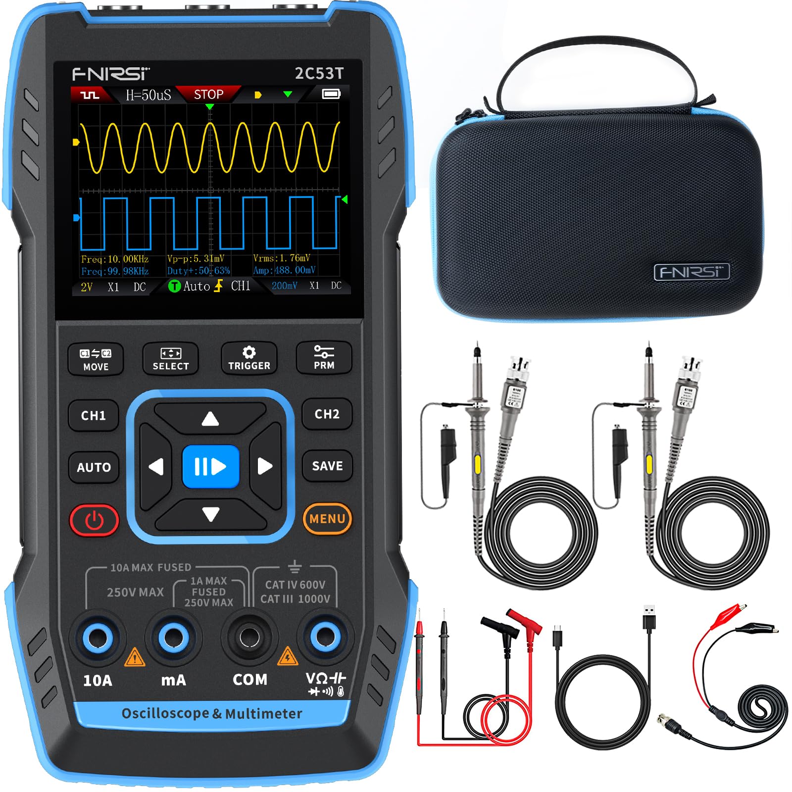
Image 3.1: The FNIRSI 2C53T device along with its standard accessories, including oscilloscope probes and multimeter test leads.
4. Setup and Initial Use
4.1 Charging the Device
Before first use, fully charge the internal lithium-ion battery. Connect the supplied Type-C USB cable to the device's Type-C port and to a 5V/1A USB power adapter (not included). The charging indicator on the screen will show the charging status.
4.2 Power On/Off
Press and hold the power button (usually marked with a power symbol) for a few seconds to turn the device ON or OFF.
4.3 Connecting Probes and Test Leads
The device features dedicated input ports for oscilloscope channels (CH1, CH2) and the signal generator (DDS), as well as multimeter input jacks (10A, mA, COM, VΩ+). Ensure correct connections for the desired function.

Image 4.1: Close-up view of the FNIRSI 2C53T's input ports, including CH1, CH2 for oscilloscope, and DDS for signal generator output.
5. Operating Instructions
The FNIRSI 2C53T features a user-friendly interface with a central navigation pad and dedicated function buttons (MOVE, SELECT, TRIGGER, PRM, AUTO, SAVE, MENU, CH1, CH2).
5.1 Oscilloscope Mode
To enter Oscilloscope mode, ensure the device is powered on. The default screen often displays the oscilloscope interface. Use the CH1 and CH2 buttons to enable or disable channels.
- Adjusting Parameters: Use the navigation pad (up/down/left/right) to select and adjust parameters like vertical sensitivity (V/div), horizontal time base (s/div), and trigger level. The 'SELECT' button confirms selections.
- Trigger Settings: Press the 'TRIGGER' button to access trigger settings, including trigger mode (Auto, Normal, Single), trigger type (Edge, Pulse, Video), and source.
- Automatic Measurement: Press 'AUTO' for automatic waveform scaling and measurement display.
- Waveform Analysis: The device supports various analysis functions. Access these through the 'MENU' button or dedicated options. These include Math Operations, Cursor Functions for precise measurements, Infinite Afterglow for observing signal changes over time, X-Y Mode for phase relationship analysis, and FFT Spectrum for frequency domain analysis.
- Saving Waveforms: Press the 'SAVE' button to store the current waveform display. Saved images can be transferred to a PC via the Type-C connection.

Image 5.1: The FNIRSI 2C53T displaying various waveform analysis features, including Math Operations, Cursor Functions, Infinite Afterglow, and X-Y Mode.
5.2 Multimeter Mode
To switch to Multimeter mode, press the 'MENU' button and navigate to the Multimeter option, or use a dedicated button if available. Connect the test leads to the appropriate input jacks (COM and VΩ+ for voltage/resistance/capacitance, 10A or mA for current).
- Voltage Measurement (AC/DC): Select ACV or DCV. Connect test leads in parallel with the circuit or component.
- Current Measurement (AC/DC): Select ACA or DCA. Connect test leads in series with the circuit. Ensure the correct current input jack (10A or mA) is used.
- Resistance Measurement: Select Ω. Connect test leads across the component when the circuit is de-energized.
- Capacitance Measurement: Select F. Connect test leads across the capacitor when the circuit is de-energized.
- Continuity Test: Select the continuity symbol. The device will emit an audible beep if continuity is detected.

Image 5.2: The FNIRSI 2C53T displaying its multimeter interface, showing voltage measurement and input jack labels.
5.3 Signal Generator Mode
To access the Signal Generator, press the 'MENU' button and select the Signal Generator option. Connect the DDS output to the circuit where the signal is needed.
- Waveform Selection: Use the navigation pad to choose from 13 available waveforms (e.g., Sine Wave, Square Wave, Sawtooth Wave).
- Parameter Adjustment: Adjust frequency, amplitude, and duty cycle (for certain waveforms) using the navigation pad and 'SELECT' button.

Image 5.3: The FNIRSI 2C53T displaying the various waveforms available from its DDS signal generator function.
6. Maintenance
6.1 Cleaning
Wipe the device with a soft, damp cloth. Do not use abrasive cleaners or solvents. Ensure the device is powered off and disconnected from all circuits before cleaning.
6.2 Battery Care
To prolong battery life, avoid fully discharging the battery frequently. If storing the device for an extended period, charge it to approximately 50% and recharge every few months.
6.3 Storage
Store the device in a cool, dry place, away from direct sunlight and extreme temperatures. Use the provided carrying case for protection during transport and storage.
7. Troubleshooting
- Device does not power on: Ensure the battery is charged. Connect the Type-C cable to a power source and try again.
- No waveform displayed in Oscilloscope mode: Check probe connections. Ensure the trigger settings are appropriate for the signal being measured. Adjust vertical and horizontal scales.
- Incorrect multimeter readings: Verify test lead connections to the correct input jacks and ensure the correct measurement function is selected. Check if the circuit is de-energized for resistance and capacitance measurements.
- Signal generator not outputting: Confirm the DDS output is connected correctly and the signal generator function is active with appropriate parameters set.
- Screen frozen or unresponsive: Try restarting the device by holding the power button. If the issue persists, contact customer support.
8. Specifications
| Feature | Specification |
|---|---|
| Model | FNIRSI 2C53T |
| Oscilloscope Channels | 2 |
| Analog Bandwidth | 50 MHz |
| Sampling Rate | 250 MSa/s |
| Record Depth | 1 Kpts |
| Max Input Voltage | 400 V |
| Vertical Sensitivity | 10 mV/div - 10 V/div |
| Multimeter Digits | 4.5 |
| Multimeter Counts | 19999 |
| AC Voltage Range | 0-750 V |
| DC Voltage Range | 0-999.9 V |
| DC/AC Current Range | 0-9.999 A |
| Resistance Range | 0-19.99 MΩ |
| Capacitance Range | 0-99.99 mF |
| Signal Generator Max Freq. | 50 kHz |
| Signal Generator Waveforms | 13 types |
| Display | 2.8-inch LCD |
| Battery | 3000 mAh Li-ion |
| Standby Time | Up to 6 hours |
| Charging Interface | Type-C (5V/1A) |
| Dimensions | 21.3 x 14.1 x 9.9 cm |
| Weight | 890 g |
9. Warranty and Support
The FNIRSI 2C53T comes with a standard manufacturer's warranty. For warranty claims, technical support, or service inquiries, please contact your point of purchase or the official FNIRSI customer support channels. Keep your purchase receipt as proof of purchase.


