1. Product Overview
The Eletechsup NT57B08 is an 8-channel Modbus RTU data collector designed for temperature and resistance measurement. It supports NTC thermistors for temperature sensing and can also directly measure resistance values from 1K to 200K ohms. This module is suitable for various applications including IoT, agricultural monitoring, and industrial control systems.
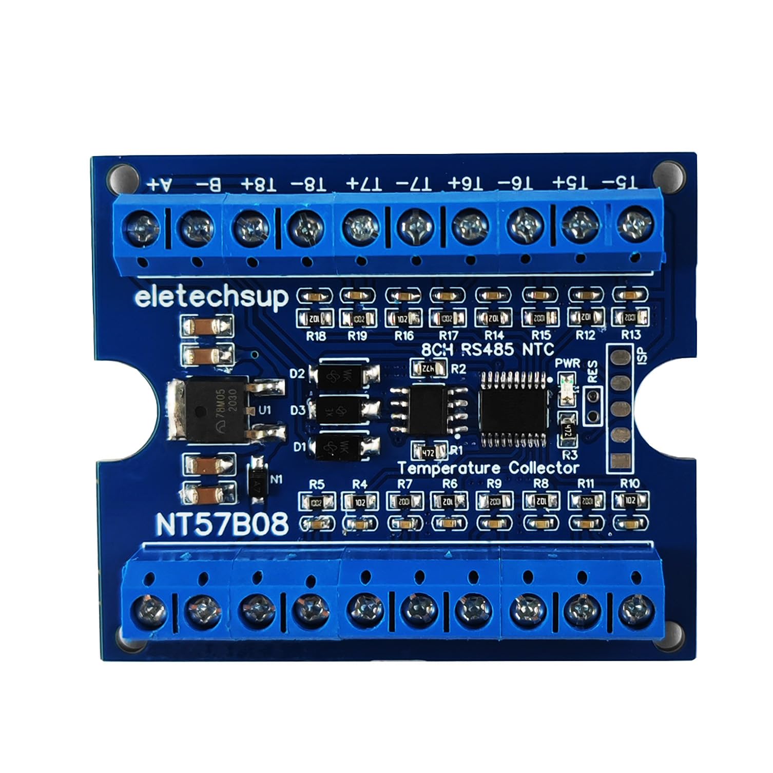
Figure 1: Eletechsup NT57B08 8-Channel Modbus RTU Data Logger (Board Only)
2. Key Features
- Standard MODBUS RTU Protocol: Ensures compatibility with a wide range of industrial control systems.
- Wide Voltage Power Supply: Operates on DC 7-25V.
- Configurable Communication Parameters: Supports multiple baud rates (2400, 4800, 9600, 19200, 38400, 57600, 115200BPS) and parity settings (NONE/EVEN/ODD).
- 8-Channel Input: Simultaneously monitors up to 8 NTC thermistor sensors or resistance values.
- Dual Measurement Capability: Measures both temperature (-20°C to +125°C) using NTC sensors and resistance (1K-200K ohms).
- High Accuracy: Temperature measurement accuracy of 1% (with recommended NTC sensors).
- TVS Surge Protection: Integrated protection for the RS485 interface.
3. Setup and Wiring
Proper wiring is essential for the correct operation of the NT57B08 module. Refer to the diagrams below for connection details.
3.1 Board Layout and Interfaces
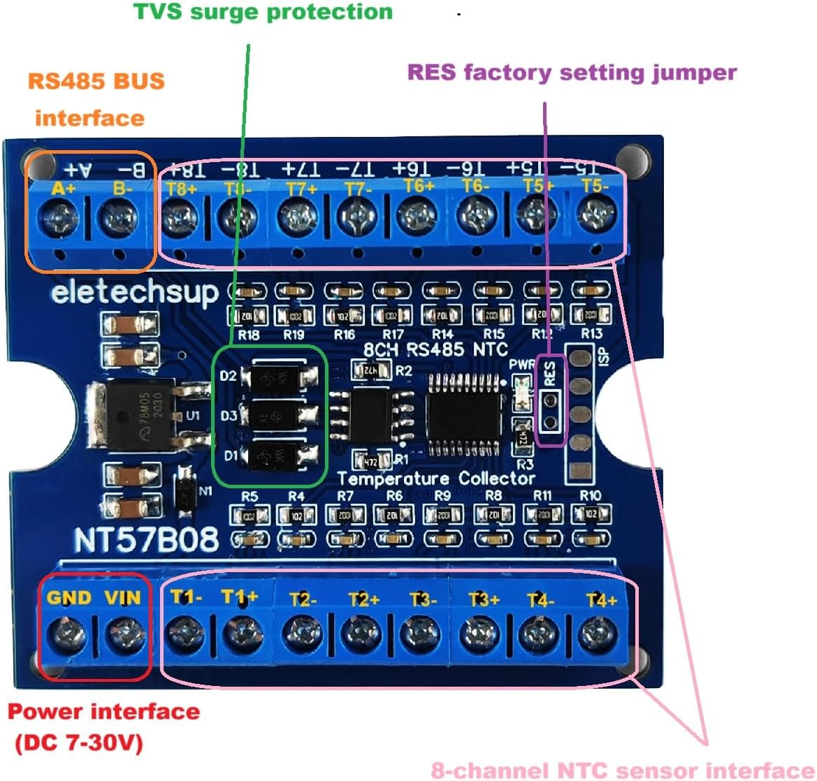
Figure 2: NT57B08 Board Layout showing Power, RS485, and Sensor Interfaces. The board features a DC 7-30V power input (GND, VIN), an RS485 BUS interface (A+, B-), and 8 channels for NTC sensors or resistance measurement (T1-T8 with corresponding + and - terminals). TVS surge protection is integrated for the RS485 bus.
3.2 NTC Temperature Measurement Wiring
Connect NTC thermistor sensors to the designated T1-T8 terminals. Ensure correct polarity if applicable, though NTC sensors typically do not have strict polarity requirements. The recommended NTC parameter is 10K B3950 1%, with a cable length range of up to 10 meters.
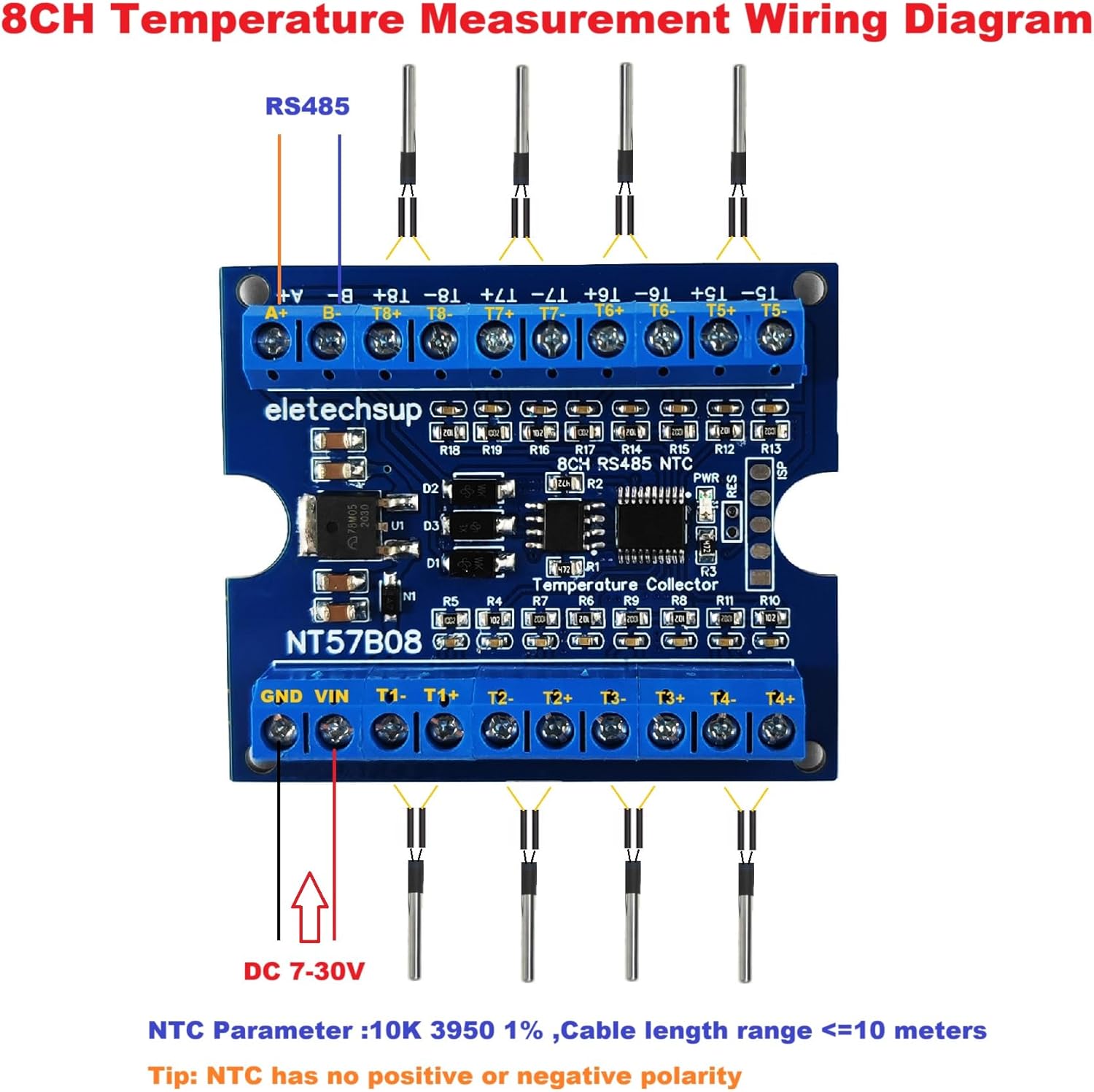
Figure 3: Wiring diagram for connecting 8 NTC temperature sensors to the NT57B08 module. Power is supplied via DC 7-30V, and communication is established via RS485. Each NTC sensor connects to a pair of T terminals (e.g., T1- and T1+).
3.3 Resistance Measurement Wiring
To measure resistance, connect the resistors directly to the T1-T8 terminals. The module supports resistance measurements in the range of 1K to 200K ohms.
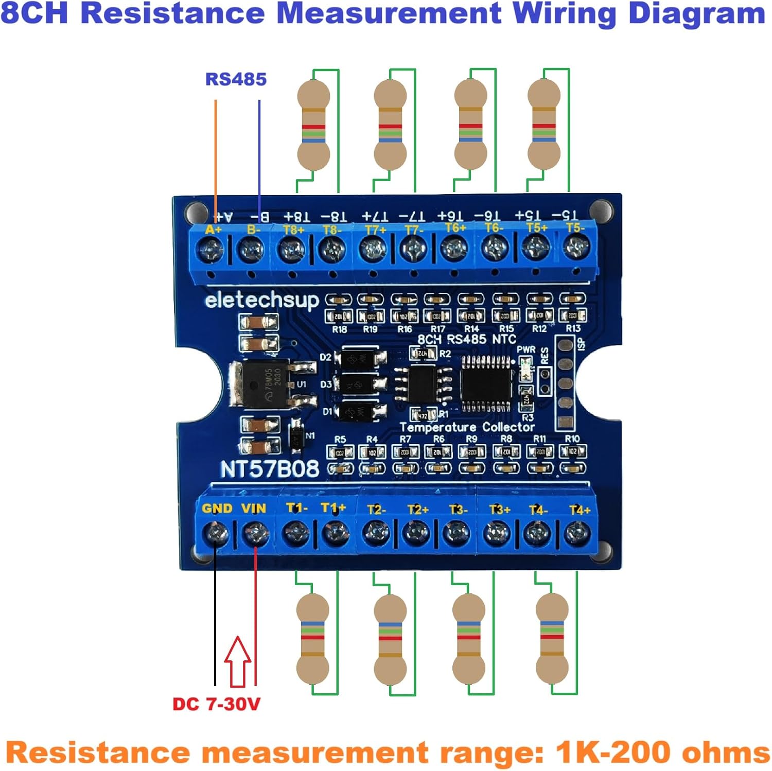
Figure 4: Wiring diagram for connecting 8 resistors for resistance measurement to the NT57B08 module. Power is supplied via DC 7-30V, and communication is established via RS485. Each resistor connects to a pair of T terminals (e.g., T1- and T1+).
4. Operating Instructions
The NT57B08 operates using the standard MODBUS RTU protocol over an RS485 interface. Communication parameters can be configured to match your system requirements.
4.1 Communication Parameters
- Default Baud Rate: 9600 BPS
- Configurable Baud Rates: 2400, 4800, 9600, 19200, 38400, 57600, 115200 BPS
- Parity Settings: NONE, EVEN, ODD
- MODBUS Function Codes Supported: 03 (Read Holding Registers), 04 (Read Input Registers), 06 (Write Single Register), 16 (Write Multiple Registers).
Refer to the specific MODBUS RTU documentation for the NT57B08 (not provided in this manual) for detailed register addresses and command structures to read temperature/resistance values and configure device settings.
4.2 Data Acquisition
Once connected and configured, the module will continuously acquire data from the connected NTC sensors or resistors. This data can be read by a master device (e.g., PLC, microcontroller, PC with RS485 adapter) using the appropriate MODBUS RTU commands.
5. Maintenance
The NT57B08 module is designed for reliable operation with minimal maintenance. To ensure longevity and accurate performance:
- Keep the board clean and free from dust and debris.
- Avoid exposure to moisture, extreme temperatures, or corrosive environments.
- Ensure all connections are secure and free from corrosion.
- Periodically inspect wiring for any signs of damage.
6. Troubleshooting
If you encounter issues with the NT57B08 module, consider the following troubleshooting steps:
- No Power: Verify the DC 7-25V power supply connection and ensure the voltage is within the specified range. Check for proper polarity.
- Communication Errors:
- Check RS485 A+ and B- connections for correct polarity.
- Ensure the baud rate and parity settings on the module match those of the master device.
- Verify the MODBUS address of the module.
- Inspect RS485 wiring for continuity and shorts.
- Incorrect Readings:
- Confirm that the correct type of NTC sensor (10K B3950 1%) is used for temperature measurement.
- Check sensor connections for looseness or damage.
- Ensure the sensor cable length does not exceed the recommended 10 meters.
- For resistance measurement, verify the resistor values are within the 1K-200K ohm range.
- Intermittent Operation: Check for stable power supply and secure connections. Environmental factors like electromagnetic interference might also affect performance.
7. Specifications
| Parameter | Value |
|---|---|
| Model | NT57B08 |
| Operating Voltage | DC 7-25V |
| Operating Current | 10-16mA (depending on external NTCs) |
| Communication Protocol | MODBUS RTU |
| Communication Interface | RS485 |
| Baud Rates | 2400, 4800, 9600 (default), 19200, 38400, 57600, 115200 BPS |
| Parity | NONE, EVEN, ODD |
| Adapted Sensor | 10K B3950 1% NTC Thermistor |
| Temperature Measurement Range | -20°C to +125°C |
| Temperature Measurement Accuracy | ±1% (with recommended NTC sensor) |
| Resistance Measurement Range | 1K-200K ohms |
| Channels | 8-channel |
| Dimensions (Board Only) | 59 x 50 x 14 mm |
| Weight (Board Only) | 27g |
7.1 NTC Sensor Specifications (Example)
The following specifications apply to compatible NTC waterproof probes:
- Product Name: 4*25mm NTC Waterproof Probe
- Resistance Value: 10K
- Resistance Accuracy: ±1%
- Resistance B Value: 3950 ± 1%
- Temperature Range: -20°C to +125°C
- Wire Size: 2651 26# parallel line, temperature 105°C
- Plug Model: Tinned tail

Figure 5: Example of a 0.5M NTC Waterproof Probe. This image illustrates the physical appearance and key specifications of a compatible NTC sensor.

Figure 6: Example of a 2M NTC Waterproof Probe. Similar to the 0.5M version, but with a longer cable, suitable for different installation distances.

Figure 7: Example of a 5M NTC Waterproof Probe. This longer probe offers extended reach for temperature monitoring applications.