1. Introduction
The Neoteck Clamp Meter MY2610C is a versatile 4000-count digital multimeter designed for precise electrical measurements. It features True RMS (TRMS) technology for accurate readings of complex waveforms and offers a wide range of functions including AC current, AC/DC voltage, resistance, capacitance, continuity, diode testing, NCV (Non-Contact Voltage) detection, and temperature measurement. This manual provides essential information for safe and effective operation of your device.
2. Safety Information
Always adhere to safety precautions when using electrical testing equipment. Failure to do so may result in electric shock, injury, or damage to the meter or equipment under test.
- This clamp meter meets CAT III 600V safety standards. Ensure all measurements are within the specified voltage and current ratings.
- Do not attempt to measure current on multiple wires simultaneously within the clamp jaw; accurate readings require measuring a single wire.
- Always inspect the test leads for damage before use. Replace damaged leads immediately.
- Use the Non-Contact Voltage (NCV) function to detect live wires without direct contact, enhancing safety.
- The meter activates an LED alarm for AC voltage between 90-1000V or live wires.
- The display will show "OL" (Overload) during an overload condition. Disconnect immediately.
- Ensure ambient temperature is within 0°C to 40°C for accurate current measurements.
- Never operate the meter if the battery cover is not securely closed.
3. Product Overview
The Neoteck Clamp Meter MY2610C is designed for ease of use and reliability across various applications, from household troubleshooting to automotive and industrial electrical diagnostics.

Figure 3.1: Front and Rear View of the Clamp Meter with Labeled Components. Key features include the NCV Sensor Probe, Clamp Body Light, Jaw Assembly, Safety Barrier, Jaw Trigger, Rotary Range Selector, Data Hold button, LCD Backlight button, LED Flashlight button, SEL Mode button, LCD Display Screen, Com Terminal, and Input Terminal.
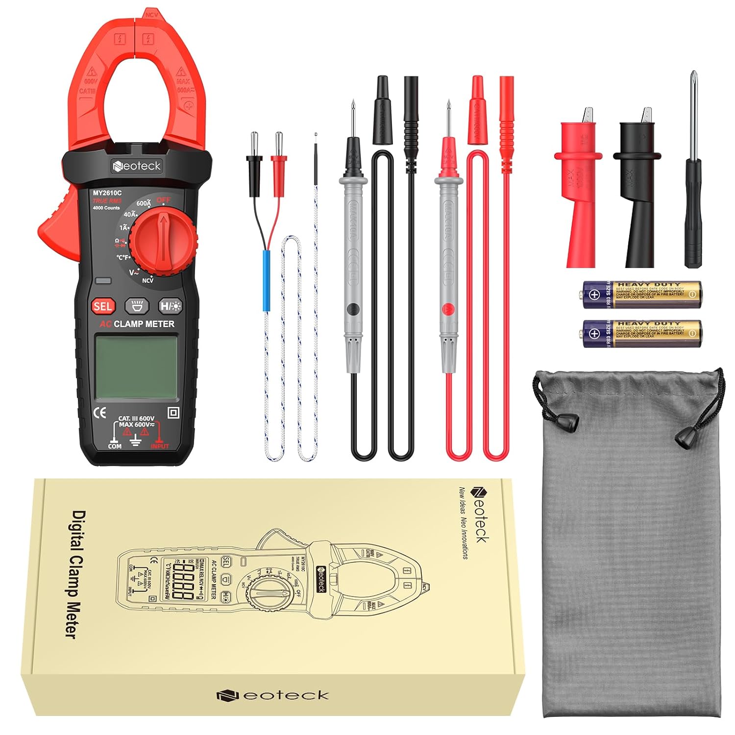
Figure 3.2: Package Contents. Includes 1x Clamp Meter, 1x Test Leads, 1x K-Type Thermocouple, 3x 1.5V AAA Batteries, 1x User Manual, 1x Pouch, 1x Alligator Clip (1 pair), and 1x Screwdriver.
Key Features:
- 4000 Counts Display: Provides high-resolution readings.
- True RMS (TRMS): Ensures accurate measurements for non-sinusoidal waveforms.
- Multi-functional: Measures AC Current (up to 600A), AC/DC Voltage (up to 600V), Resistance, Capacitance, Continuity, Diode, NCV, and Temperature.
- NCV Detection: Non-contact voltage detection for enhanced safety.
- Temperature Measurement: Via K-type thermocouple, ranging from -40°C to 1000°C.
- User-Friendly Design: Backlit LCD, flashlight, data hold, auto-ranging, and auto power-off.
- Compact and Portable: Lightweight design with a soft storage pouch.
4. Setup
4.1 Battery Installation
- Locate the battery compartment on the back of the meter.
- Use the included screwdriver to open the battery cover.
- Insert three 1.5V AAA batteries, ensuring correct polarity (+/-).
- Securely close the battery cover and tighten the screw.
4.2 Connecting Test Leads
- For voltage, resistance, capacitance, continuity, and diode tests, insert the red test lead into the "INPUT" terminal and the black test lead into the "COM" terminal.
- For temperature measurements, connect the K-type thermocouple to the designated ports, observing polarity if indicated.
5. Operating Instructions
5.1 Power On/Off
Rotate the central dial from the "OFF" position to any desired measurement function to power on the meter. To power off, rotate the dial back to "OFF". The meter also features an auto power-off function after 15 minutes of inactivity to conserve battery life.
5.2 Function Selection
Use the rotary dial to select the primary measurement mode (e.g., AC Current, Voltage, Resistance). For functions with multiple sub-modes (e.g., AC/DC Voltage, Resistance/Continuity/Diode/Capacitance), press the SEL button to cycle through the available options.
5.3 AC Current Measurement
- Rotate the dial to the "600A" or "40A" AC current range.
- Press the jaw trigger to open the clamp.
- Enclose only a single conductor within the clamp jaw. Ensure the conductor is centered for accurate readings.
- Read the AC current value on the LCD display.
- Important Note: Clamp meters only support single-wire current measurement. Measuring multiple wires will result in inaccurate readings.

Figure 5.1: Measuring AC Current. The 25mm large jaw clamp allows for direct cable measurement without cutting. Note the requirement for single-wire measurement for accuracy.

Figure 5.2: Clamp Meter in use within an electrical panel, demonstrating current measurement on a single conductor.
5.4 AC/DC Voltage Measurement
- Rotate the dial to the "V~" (AC Voltage) or "V-" (DC Voltage) position.
- Connect the red test lead to the positive point and the black test lead to the negative point or ground of the circuit.
- Read the voltage value on the LCD display.
5.5 Resistance, Continuity, Diode, and Capacitance Measurement
- Rotate the dial to the "Ω" (Resistance) position.
- Press the SEL button to cycle through Resistance (Ω), Continuity (buzzer icon), Diode (diode symbol), and Capacitance (capacitor symbol) modes.
- Connect the test leads across the component or circuit to be measured.
- For continuity, the meter will beep if a continuous path is detected.
- For diode testing, the forward voltage drop will be displayed.

Figure 5.3: Demonstrating various measurement functions including Resistance, Continuity, Capacitance, and Diode testing on electronic components.
5.6 NCV (Non-Contact Voltage) Detection
- Rotate the dial to the "NCV" position.
- Move the NCV sensor probe (top of the clamp jaw) close to the conductor or outlet.
- The meter will emit an audible alarm and the LED will flash when AC voltage between 90-1000V is detected.

Figure 5.4: NCV Function in use, detecting voltage near an electrical outlet. The meter provides audible and visual alarms for safety.
Video 5.1: Demonstration of various functions including NCV, DC Voltage, Resistance, Continuity, and Temperature measurement. Note: This video features a Neoteck 6000 Counts 800A/600V Digital Clamp Meter, which may have slightly different specifications than the MY2610C model.
5.7 Temperature Measurement
- Rotate the dial to the "°C/°F" position.
- Connect the K-type thermocouple to the input terminals.
- Place the thermocouple probe on or in the object whose temperature is to be measured.
- Read the temperature on the LCD display. Press SEL to switch between Celsius and Fahrenheit.
Figure 5.5: Temperature measurement using the K-type thermocouple. The meter can measure temperatures from -40°C to 1000°C.
5.8 Additional Features
- Backlit LCD & Flashlight: Press the H/* button to activate the backlight and flashlight for use in dark environments.
- Data Hold: Press the H/* button briefly to hold the current reading on the display. Press again to release.
- Auto-Ranging: The meter automatically selects the appropriate measurement range for most functions.

Figure 5.6: Thoughtful design features such as Auto-Off, Data Hold, Flashlight, and LCD Backlight for improved user experience.
6. Maintenance
6.1 Cleaning
- Wipe the meter's casing with a damp cloth and mild detergent. Do not use abrasives or solvents.
- Keep the test leads and terminals clean and free from dust or debris.
6.2 Battery Replacement
When the low-battery indicator appears on the display, replace the batteries as described in the "Battery Installation" section (4.1). Always use fresh 1.5V AAA batteries.
6.3 Storage
Store the meter in its soft storage pouch in a cool, dry place away from direct sunlight and extreme temperatures. Remove batteries if the meter will not be used for an extended period.
7. Troubleshooting
| Problem | Possible Cause | Solution |
|---|---|---|
| Meter does not power on. | Dead or incorrectly installed batteries. | Check battery polarity and replace batteries if necessary. |
| "OL" displayed during measurement. | Overload condition; measurement exceeds selected range. | Select a higher range or disconnect from the circuit if the maximum range is exceeded. |
| Inaccurate AC current reading. | Multiple wires in the clamp jaw; ambient temperature outside 0°C to 40°C. | Ensure only a single wire is within the clamp. Perform measurement within the specified temperature range. |
| NCV function not responding. | Voltage too low or not present; sensor not close enough. | Ensure the NCV sensor is directly over the live conductor. Verify voltage presence by other means if possible. |
8. Specifications
| Feature | Specification |
|---|---|
| Display | 4000 Counts |
| Safety Rating | CAT III 600V |
| AC Current (ACA) | 1A/40A/600A ±(2.5%+10) |
| DC Voltage (DCV) | 400mV/4V/40V/400V/600V ±(0.8%+2) |
| AC Voltage (ACV) | 4V/40V/400V/600V ±(1.0%+10) |
| Resistance | Up to 40MΩ ±(1.2%+2) |
| Capacitance | Up to 40mF |
| Temperature Range | -40°C to 1000°C (-40°F to 1832°F) ±(1.0%+5) |
| Jaw Opening | 25mm |
| Power Source | 3 x 1.5V AAA Batteries (included) |
| Dimensions | 18 x 7 x 3.5 cm |
| Weight | 350 g |
9. Warranty and Support
Neoteck products are designed for reliability and performance. For warranty information, technical support, or service inquiries, please refer to the contact details provided in the product packaging or visit the official Neoteck website. Keep your purchase receipt as proof of purchase for warranty claims.


