
1. Introduction
This manual provides detailed instructions for the installation, operation, and maintenance of your Haeweypf 36V 48V Ebike Controller Kit. This kit includes a 750W-1000W 30A brushless motor controller and an S966 color LCD display. Please read this manual thoroughly before use to ensure proper function and safety.
2. Product Features
- Outstanding Performance: Crafted with professional technology and premium materials, this brushless motor controller offers powerful torque, strong climbing capability, robust power, steady speed, and low noise.
- Intelligent Protection Systems: Features overcurrent, undervoltage, and overheating protection to extend motor and battery lifespan, save energy, and ensure efficient, reliable motor performance.
- Wide Compatibility (3-Mode Sine Wave Controller): Sensitively controls braking and direction changes. Compatible with both Hall sensor and sensorless brushless motors. Engages sine wave control with functional Hall sensors; switches to square wave mode if Hall sensors fail or are absent, ensuring seamless motor operation.
- Smart Ebike Color LCD Display (S966): Bright, clear, large screen for easy reading of riding speed, battery level, cruise control, and assist levels. Customizable display panel. Equipped with NFC key card unlocking and password protection (default initial password: "2023") for enhanced security.
- Efficient Heat Dissipation: The controller features an aluminum alloy grooved housing designed for rapid heat dissipation, ensuring stable performance.
3. Specifications
| Feature | Specification |
|---|---|
| Voltage | 36V, 48V, 52V, 60V (Controller) / 48V (Product Listing) |
| Power | 750W-1000W |
| Current | 30A ± 1 |
| Mosfet | 12 Mos |
| Brakes | Low Level |
| Type | Brushless DC |
| Controller Weight | Approx. 450g |
| Controller Size | 5.79 x 2.24 x 1.30 inches (147 x 57 x 33 mm) |
| Display Model | S966 |
| Display Shell Material | ABS |
| Display Gear Mode | 1-3 |
| Display Net Weight | 300g |
| Display Matching Voltage | 24V/36V/48V |
| Display Waterproof Grade | IP65 |
| Material Type | Aluminum (Controller Housing) |
Note: Due to manual measurement, slight variations (1-3 mm) in controller dimensions may occur.
4. What's in the Box
- 1 × Ebike Brushless Controller
- 1 × S966 LCD Display
5. Setup & Installation
Proper installation is crucial for the safe and efficient operation of your ebike controller kit. Follow these steps carefully.
5.1. Wiring Diagram
Refer to the detailed wiring diagram below to identify each connector and ensure correct connections. Different manufacturers may use varying connectors; if your controller's connectors do not match, professional assistance may be required to adapt them. If wire colors differ, adjust the wiring sequence per the definitions provided.

Image: Detailed wiring diagram for the Haeweypf ebike controller kit.
5.2. Installation Steps
- Step 1: Connect the Battery and Motor
- Connect the controller power wire to the battery. Caution: Ensure correct positive and negative pole connections.
- Connect the controller to the motor. The motor phase wires and motor Hall wires should be connected one by one. If no Hall sensor wires are present, leave them unconnected.
- Connect the controller to the instrument (display).
After completing these three steps, proceed to use the self-learning wire to match the motor.
- Step 2: Self-learning Motor Matching
(Self-learning is valid within 2 minutes of startup. It needs to be turned off and restarted after more than 2 minutes.)
- Power on the meter (long press the power button of the meter for 3 seconds to power on).
- Locate the two white self-learning wires on the controller and plug them into each other. Note: The motor will rotate after the self-learning wires are plugged in. The motor wheel must be suspended beforehand to prevent speeding.
- Allow the motor to rotate for 10 seconds, then directly disconnect the two self-learning wires from each other. Do not turn off or power off the system during this process.
After completing the above steps, the motor matching is complete. The test motor can now be connected to the throttle. For other functions, connect according to the definition of the controller socket (unneeded functions can be left blank), ensuring no incorrect connections.

Image: Product Installation Steps for the controller and display.
5.3. Self-learning Wire Guide
The self-learning wires are essential for initial setup to ensure compatibility between the controller and your motor.

Image: Guide to the Self-learning Wire of the Controller.
- Purpose: To match a replacement controller with your motor's internal phase and Hall wire sequences, resolving compatibility issues.
- Usage: Connect the two white self-learning wires together. If the motor rotates forward, the self-learning is complete; disconnect the wires. If the motor doesn't run, spins backward, or makes buzzing noises, disconnect and reconnect the wires to restart pairing.
- Duration: Keep connected for approximately 10 seconds during the learning process.
- Disconnection: The self-learning wires must be disconnected after the self-learning process is completed. Never leave them connected permanently.
5.4. Installation Video Guide
For a visual guide on the installation process, please watch the official video below:
Video: Installation steps for the 30A 750W/1000W Brushless Controller. This video demonstrates the connection process and self-learning procedure.
6. Operating Instructions (S966 LCD Display)
The S966 color LCD display provides comprehensive information and allows for various settings adjustments.
6.1. Display Overview and Key Operations
The display shows key riding data and allows interaction via three buttons: Plus key, M key, and Minus key.
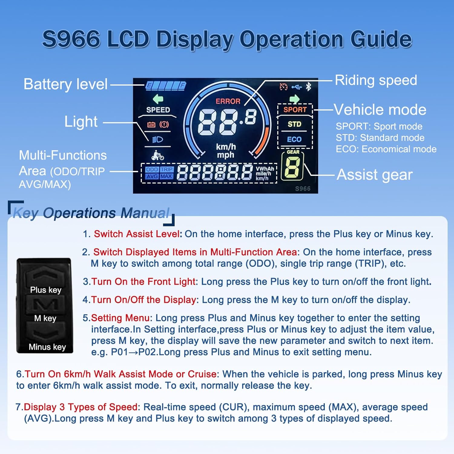
Image: S966 LCD Display Operation Guide.
- Switch Assist Level: On the home interface, press the Plus key or Minus key.
- Switch Displayed Items in Multi-Function Area: On the home interface, press the M key to switch among total range (ODO), single trip range (TRIP), average speed (AVG), maximum speed (MAX), riding time, and current battery voltage.
- Turn On the Front Light: Long press the Plus key to turn on/off the front light.
- Turn On/Off the Display: Long press the M key to turn on/off the display.
- Setting Menu: Long press Plus and Minus keys together to enter the setting interface. In the setting interface, press Plus or Minus key to adjust the item value. Press M key to save the new parameter and switch to the next item. Long press Plus and Minus to exit the setting menu.
- Turn On 6km/h Walk Assist Mode or Cruise: When the vehicle is parked, long press the Minus key to enter 6km/h walk assist mode. To exit, normally release the key.
- Display 3 Types of Speed: Real-time speed (CUR), maximum speed (MAX), average speed (AVG). Long press M key and Plus key to switch among these 3 types of displayed speed.
6.2. Parameter Settings (P-Settings)
The display menu provides a total of 20 parameters (P01-P20) for configuration. Access these settings by long-pressing the Up and Down keys simultaneously.

Image: Meter "P" Parameter Setting Info.
| Parameter | Description | Range/Default |
|---|---|---|
| P01 | Backlight Brightness | 1 (darkest) - 3 (brightest) |
| P02 | Mileage Unit | 0: KM; 1: MILE |
| P03 | Voltage Level | 24V/36V (default) / 48V |
| P04 | Auto-Off Time | 0-60 (minutes); 0 means never auto-off |
| P05 | Assist Level | Normally 3 types available: 3/5/9 Levels |
| P06 | Wheel Size Unit | Inch, Precision: 0.1 |
| P07 | Magnetic Steel Number for Speed Test | Range: 1-100 |
| P08 | Speed Limit Range | 0-50km/h; parameter 50 indicates no speed limit |
| P09 | Zero / Non-Zero Start Setting | 0: Zero Start (direct start when throttle turns); 1: Non-Zero Start (kick to start) |
| P10 | Drive Mode Setting | 0: Pedal Assist Only; 1: Throttle Only; 2: Pedal Assist + Throttle |
| P11 | Assist Power Intensity | Range: 0-5 |
| P12 | PAS Sensor Magnet Steel Number | 5 / 8 / 12pcs |
| P13 | Current Limit Value | 12A by default; Range: 1-20A |
| P14 | Unspecified | |
| P15 | ODO Zero-Out | Long press the upper key for 5 seconds to reset ODO value. |
6.3. NFC Key Card Unlocking
The S966 display is equipped with NFC key card unlocking for enhanced security. The default initial password is "2023" if using password unlock.

Image: S966 Smart Display Details, including NFC key card information.
- NFC Inductive Switch: Auto power on when an NFC card is brought near the meter center.
- Password Unlock: Long-press the M key, then enter the initial password "2023" to power on.
- Two NFC cards are provided: one for daily use, and the other as a backup.
7. Maintenance
Regular maintenance helps ensure the longevity and optimal performance of your ebike controller kit.
- Keep the controller and display clean and dry. Avoid exposure to excessive moisture or direct water spray.
- Periodically check all wire connections to ensure they are secure and free from corrosion.
- Inspect the controller housing for any signs of damage or overheating.
- Ensure the display screen is free from scratches or cracks that could impair visibility.
- If any components appear damaged or worn, consult a professional for repair or replacement.
8. Troubleshooting
This section addresses common issues you might encounter with your ebike controller kit.
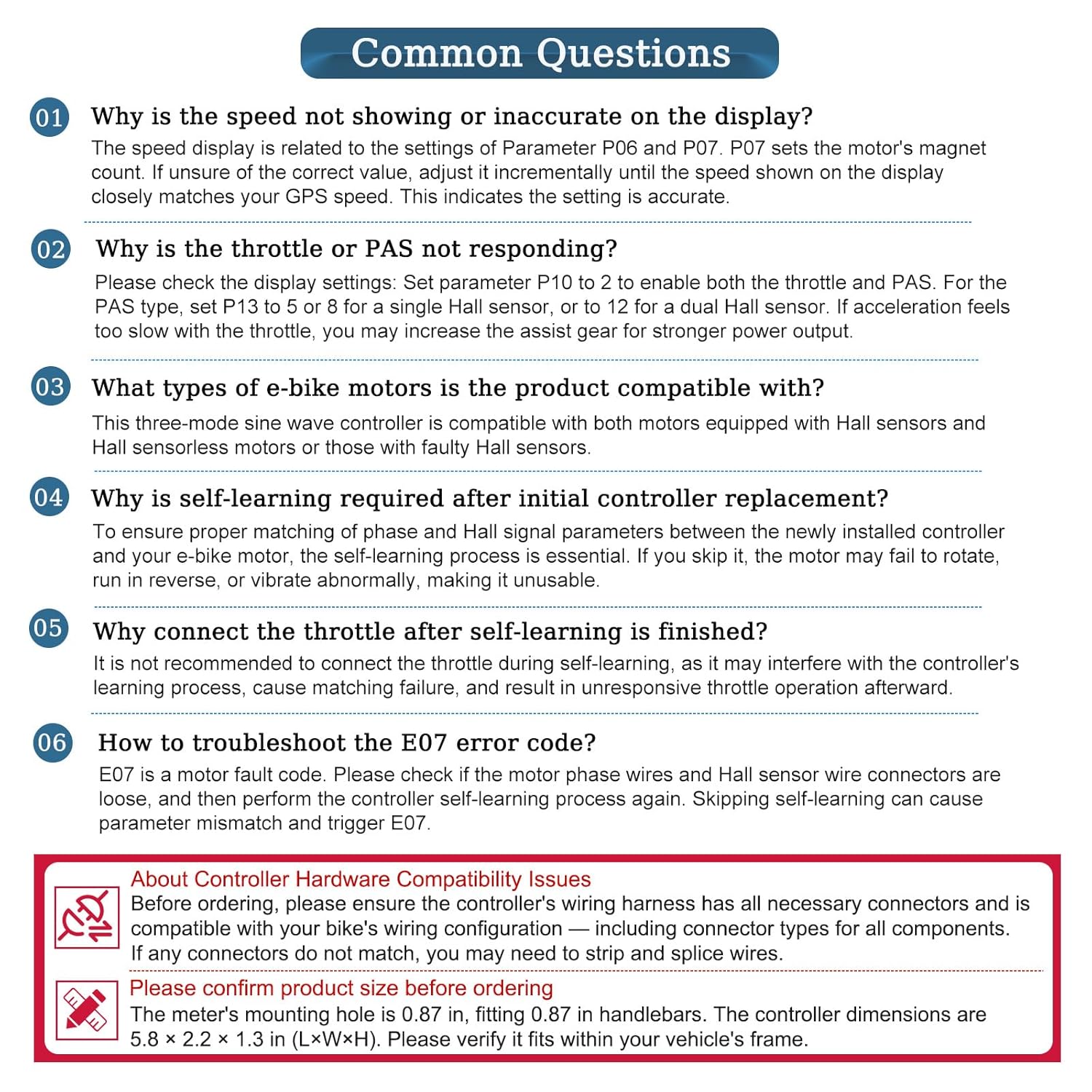
Image: Common Questions and Error Code Troubleshoot.
8.1. Common Questions
- Q1: Why is the speed not showing or inaccurate on the display?
A1: The speed display is related to parameters P06 (Wheel Size) and P07 (Magnetic Steel Number). If unsure of the correct value, adjust it incrementally until the speed shown on the display closely matches your GPS speed. This indicates the setting is accurate. - Q2: Why is the throttle or PAS not responding?
A2: Check the display settings: Set parameter P10 to 2 to enable both throttle and PAS. For the PAS type, set P13 to 5 or 8 for a single Hall sensor, or to 12 for a dual Hall sensor. If acceleration feels too slow with the throttle, you may increase the assist gear for stronger power output. - Q3: What types of e-bike motors is the product compatible with?
A3: This three-mode sine wave controller is compatible with both motors equipped with Hall sensors and Hall sensorless motors, or those with faulty Hall sensors. - Q4: Why is self-learning required after initial controller replacement?
A4: To ensure proper matching of phase and Hall signal parameters between the newly installed controller and your e-bike motor, the self-learning process is essential. Skipping it may cause the motor to fail to rotate, run in reverse, or vibrate abnormally. - Q5: Why not connect the throttle after self-learning is finished?
A5: It is not recommended to connect the throttle during self-learning, as it may interfere with the controller's learning process, cause matching failure, and result in unresponsive throttle operation afterward.
8.2. Error Code Troubleshoot (S966 Display)
| Code | Indication |
|---|---|
| 0 | Normal |
| 1 | Reserved |
| 2 | Brake |
| 3 | Power Sensor Error (riding mark) |
| 4 | Reserved |
| 5 | Reserved |
| 6 | Low Battery Voltage |
| 7 | Motor Error |
| 8 | Throttle Error |
| 9 | Controller Error |
| 10 | Communications Receiving Error |
| 11 | Communications Sending Error |
| 12 | BMS Communications Error |
| 13 | Light Error |
9. Safety Information
Always prioritize safety when installing and operating electrical components on your ebike or scooter.
- Ensure the power is disconnected from the battery before performing any installation or maintenance.
- Double-check all wiring connections to prevent short circuits or damage to components.
- If you are unsure about any part of the installation, seek assistance from a qualified technician.
- Do not modify the controller or display in any way not described in this manual.
- Keep the product away from children.
10. Warranty and Support
For warranty information and customer support, please refer to the product packaging or contact Haeweypf customer service directly. Ensure you retain your proof of purchase for any warranty claims.