1. Product Overview
This manual provides instructions for the GODIYMODULES 5mm 850nm IR LED Emitting Diode. This component is designed for various DIY electronics projects, including infrared transmitters, receivers, and PCB applications. Each package contains 100 pieces of these infrared emitting diodes.
Key Features:
- Quantity: 100 Pcs 5mm IR LED Emitting Diodes
- Wavelength: 850nm (Infrared)
- Forward Voltage: 1.4-1.6V
- Forward Current: 20mA

Image: A pack of 100 5mm IR LED emitting diodes, showing their clear casing and two leads.
2. Safety Information
Always handle electronic components with care. Avoid direct eye exposure to the infrared light, as it is not visible but can be harmful. Ensure proper current limiting resistors are used to prevent damage to the LED and power supply. Do not exceed the specified forward voltage or current. Disconnect power before making any connections or disconnections.
3. Setup and Installation
The 5mm IR LED has two leads: a longer lead (anode) and a shorter lead (cathode). The anode connects to the positive (+) terminal of your power supply, and the cathode connects to the negative (-) terminal, typically through a current-limiting resistor.
A current-limiting resistor is essential to protect the LED from excessive current. For a typical 5V power supply and a forward voltage of 1.5V, a resistor of approximately 175 ohms (R = (V_supply - V_forward) / I_forward = (5V - 1.5V) / 0.02A = 3.5V / 0.02A = 175 ohms) is recommended. Adjust the resistor value based on your specific power supply and desired current to ensure the LED operates within its specified current limits.
3.1. Polarity Identification
- Anode (+): The longer lead.
- Cathode (-): The shorter lead.
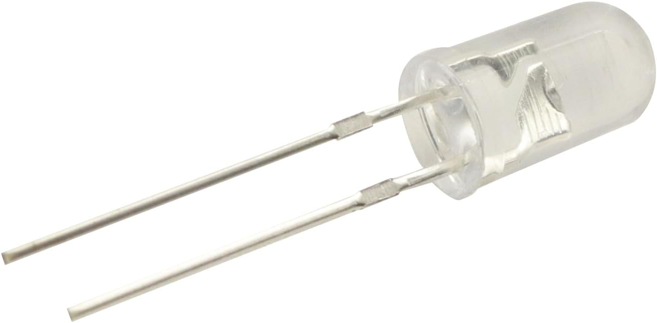
Image: A close-up view of a single 5mm IR LED, clearly showing the longer anode and shorter cathode leads for proper connection.
4. Operation
When correctly powered, the IR LED emits infrared light at a wavelength of 850nm. This light is invisible to the human eye but can be detected by infrared receivers, phototransistors, or photodiode sensors. The primary function is to transmit an infrared signal for various applications such as remote controls, object detection, or data communication.
Ensure the IR LED is aligned with the corresponding receiver for optimal signal transmission. The effective range will depend on the power supplied to the LED, the sensitivity of the receiver, and environmental factors such as ambient light interference.
5. Specifications
| Specification | Value |
|---|---|
| Brand | GODIYMODULES |
| Model Name | IR-850nm-100 |
| Light Type | 850nm IR |
| Emitting Color | Infrared (850nm) |
| Forward Voltage | 1.4-1.6V (typical) |
| Forward Current | 20mA (typical) |
| Bulb Base | Prong |
| Number of Items | 100 Pcs |
| Material | IR LED |
| Item Weight | 1.23 ounces |
| Package Dimensions | 5.2 x 4.49 x 1.06 inches |
6. Maintenance
Keep the IR LEDs in a dry, cool environment. Avoid exposing them to excessive heat, moisture, or static electricity. Handle leads carefully to prevent bending or breaking. Clean the LED lens with a soft, dry cloth if necessary to ensure optimal light emission. Store unused LEDs in their original packaging or an anti-static bag.
7. Troubleshooting
7.1. LED does not light up
- Check polarity: Ensure the anode (longer lead) is connected to positive and cathode (shorter lead) to negative. Incorrect polarity will prevent the LED from functioning.
- Verify power supply: Confirm the power supply is providing the correct voltage and sufficient current.
- Inspect current-limiting resistor: Ensure the correct resistor value is used and it is properly connected in series with the LED. An incorrect or missing resistor can prevent operation or damage the LED.
- Check for damage: Examine the LED for any physical damage, such as broken leads or a cracked casing.
7.2. Weak or inconsistent signal
- Check alignment: Ensure the IR LED is properly aligned with the receiver. Misalignment can significantly reduce signal strength.
- Verify current: Confirm the LED is receiving sufficient current (e.g., 20mA) to emit a strong infrared signal.
- Environmental interference: Minimize strong ambient light sources (e.g., direct sunlight, fluorescent lights) that might interfere with the IR signal.
- Receiver sensitivity: Ensure the receiver component is functioning correctly and is sensitive enough for the application.
8. Warranty and Support
For product support or warranty inquiries, please refer to the seller's contact information provided at the point of purchase. Keep your purchase receipt or order details for warranty validation. This product is intended for DIY and educational purposes; proper handling and circuit design are the responsibility of the user.


