Introduction
Welcome to the Briidea CO2 Controller and Monitor user manual. This document provides comprehensive instructions for the safe and efficient operation of your device. Please read this manual thoroughly before installation and use.
The Briidea CO2 Controller and Monitor is designed to precisely manage carbon dioxide levels in controlled environments such as greenhouses, grow rooms, and hydroponic setups. It features a high-precision NDIR CO2 sensor and programmable functions to optimize plant growth.
Safety Information
Read all instructions:
Ensure you understand all safety warnings and operating instructions before use.Electrical Safety:
This device operates on standard electrical power. Do not exceed the maximum power allowance of 1800W. Ensure proper grounding.Placement:
Install the controller in a dry, well-ventilated area, away from direct sunlight, heat sources, and excessive moisture.Sensor Handling:
Handle the remote CO2 sensor with care. Avoid physical shock or exposure to corrosive substances.Maintenance:
Disconnect power before performing any maintenance or cleaning.Children and Pets:
Keep the device out of reach of children and pets.
Package Contents
Verify that all items are present in the package:
- Briidea CO2 Controller Unit
- Remote CO2 Sensor (6.56 ft cable)
- Power Input Line (integrated)
- Output Socket (piggyback plug, integrated)
- Mounting Hardware (screws, double-sided adhesive tape)
- User Manual (this document)
Product Overview
The Briidea CO2 Controller and Monitor features a main control unit with a digital display, control buttons, and integrated power input/output. A remote sensor provides accurate CO2 readings.
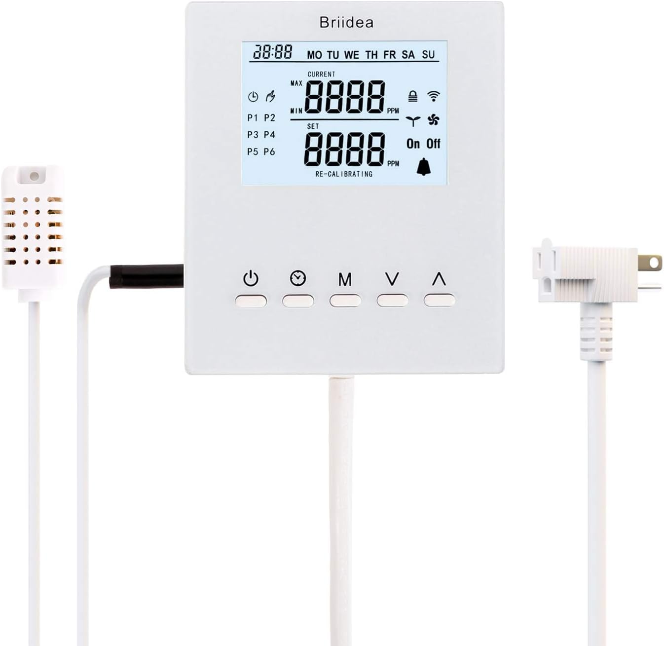
Figure 1: Briidea CO2 Controller and Monitor. This image displays the main controller unit, the remote CO2 sensor connected via a cable, and the integrated power plug with a piggyback outlet.
Key Features:
- High-precision NDIR CO2 sensor for accurate readings.
- Programmable CO2 levels for different growth stages.
- Day and Night mode settings.
- Plug-and-play operation with piggyback outlet.
- Supports up to 1800W for connected devices.
- UL-listed components for safety.
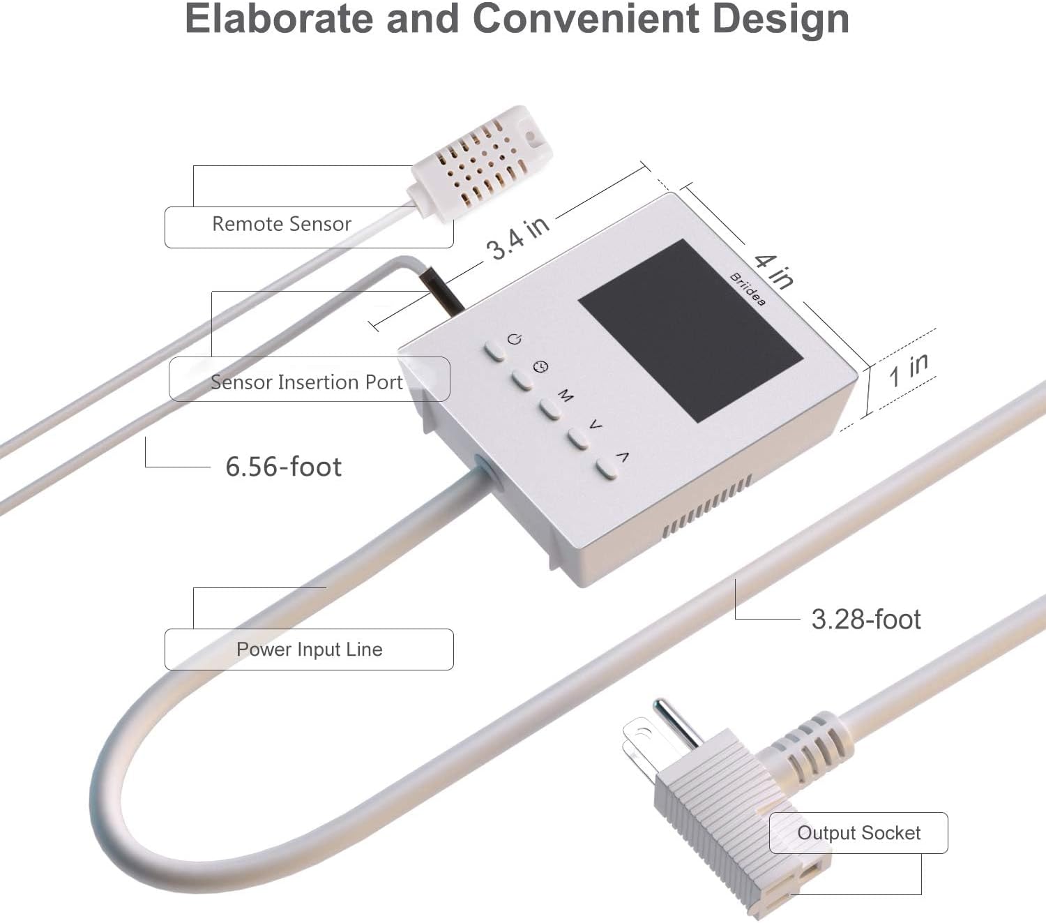
Figure 2: Detailed view of the controller's components and dimensions. This image highlights the remote sensor, sensor insertion port, power input line, output socket, and the overall dimensions of the controller unit (3.4 in x 4 in x 1 in).
Setup
1. Mounting the Controller:
The controller can be mounted using screws or double-sided adhesive tape.
- Choose a suitable location on a wall or vertical surface, ensuring it is dry and stable.
- Use the provided screws to secure the controller, or apply the double-sided adhesive tape to the back of the unit and press firmly onto the desired surface.
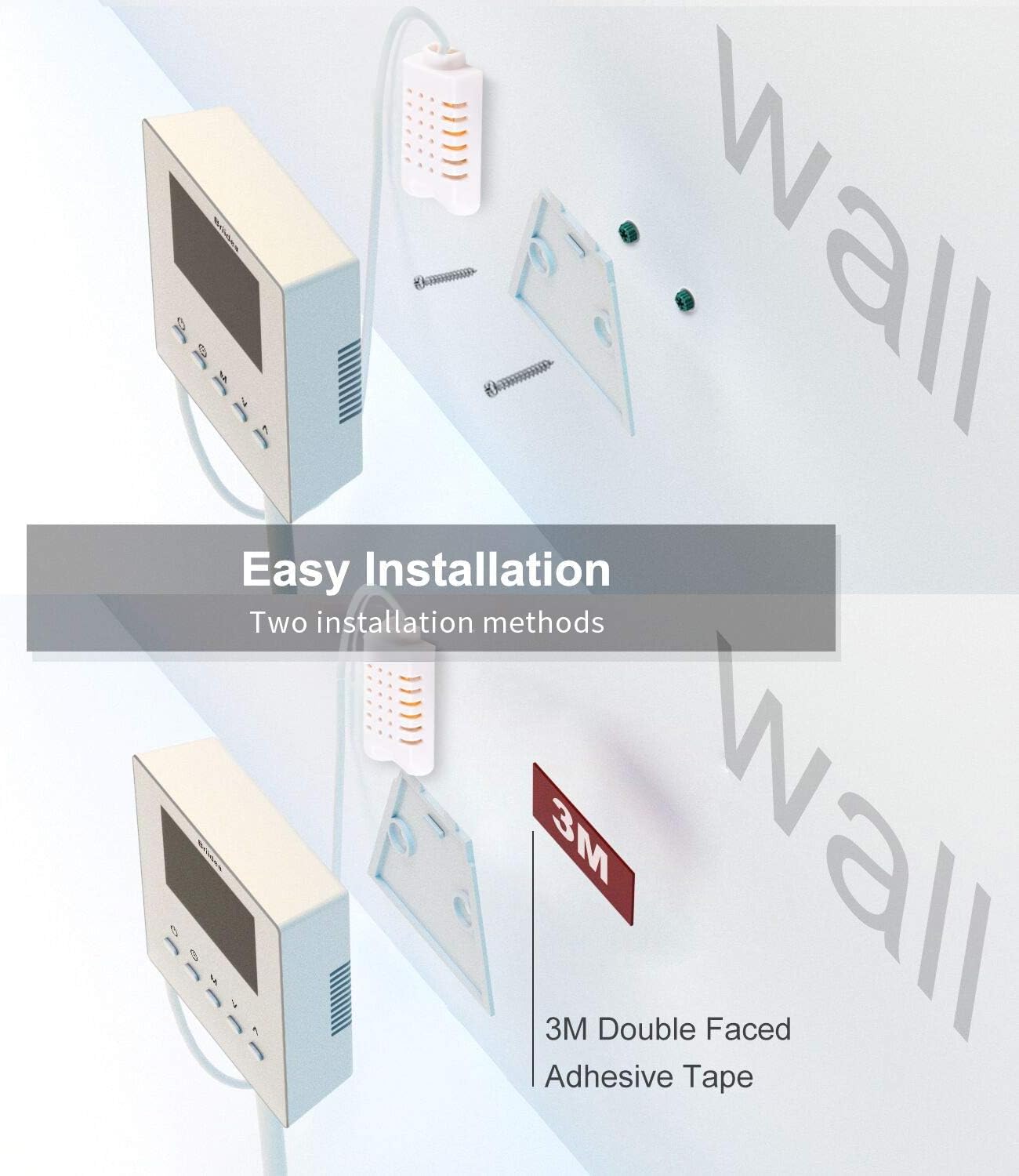
Figure 3: Installation methods for the Briidea CO2 Controller. The image shows two options: mounting with screws or using 3M double-sided adhesive tape.
2. Connecting the Remote CO2 Sensor:
Insert the remote CO2 sensor cable into the designated port on the controller unit. Position the sensor in an optimal location within your grow room or greenhouse to ensure accurate CO2 readings. The 6.56 ft cable allows for flexible placement.

Figure 4: CO2 Sensor details. This image highlights the CO2 sensor's measurement range (0-5000ppm) and its features: stable quality, long lifespan, high sensitivity, low power consumption, waterproof, anti-corrosion, and NDIR technology for precise readings.
3. Power Connection:
Plug the controller's power input line into a standard electrical outlet. The display will illuminate.
4. Connecting CO2 Device:
Plug your CO2 generator or regulator into the piggyback outlet on the controller's power plug. Ensure the connected device does not exceed the 1800W power limit.

Figure 5: Connection diagram. This illustration shows the Briidea CO2 Controller connected to a CO2 tank and a fan within a grow tent setup, demonstrating how the controller manages CO2 levels and ventilation.
Operating Instructions
Display Overview:

Figure 6: Controller display. The display shows the current time, day of the week, current CO2 level (MAX/MIN), set CO2 level, and indicators for various functions like fan, alarm, and program stages (P1-P6).
Button Functions:
Power Button (⏻):
Turns the unit on/off.Mode Button (M):
Cycles through different operating modes (e.g., Greenhouse Mode, Ventilation Mode, Manual Control).Set Button (V):
Enters setting mode to adjust parameters.Up/Down Buttons (▲ / ▼):
Adjust values or navigate menu options in setting mode.
Setting Time and Day:
- Press the Set button to enter time setting mode.
- Use the Up/Down buttons to adjust the hour, then press Set to confirm and move to minutes.
- Repeat for minutes and day of the week.
- Press Mode to exit setting mode.
Greenhouse Mode (CO2 Enrichment):
In this mode, the controller activates the connected CO2 generator/regulator when CO2 levels fall below the set target and deactivates it when the target is reached.
- Press the Mode button until "Greenhouse Mode" is indicated (or similar icon).
- Press Set to enter CO2 target setting.
- Use Up/Down buttons to set the desired CO2 PPM level.
- Press Set to confirm.
- The controller will now automatically manage CO2 based on your setting.
Ventilation Mode (CO2 Reduction):
When CO2 concentration is too high, this mode activates a connected fan to reduce CO2 levels.
- Press the Mode button until "Ventilation Mode" is indicated (or similar icon).
- Press Set to enter CO2 threshold setting.
- Use Up/Down buttons to set the maximum acceptable CO2 PPM level.
- Press Set to confirm.
- The controller will activate the fan when CO2 exceeds this threshold.
Programmable Functions (P1-P6):
The controller offers 6 preset CO2 levels for different growth stages and time periods. This allows for customized CO2 management throughout the day or week.

Figure 7: Programmable function table. This image illustrates how to set start times and PPM states for six different program periods (P1-P6) across the week, including an "OFF" state for P6.
- Press Mode to cycle to the programmable settings (P1, P2, etc.).
- Press Set to configure a program stage.
- Adjust the start time and target CO2 PPM for each stage using the Up/Down buttons and Set button.
- You can also schedule CO2 shut-off during dark cycles by setting a program stage to "OFF".
- Repeat for all desired program stages (P1-P6).
Auto Mode:
This mode utilizes the programmed settings (P1-P6) to automatically adjust CO2 levels throughout the day/week.
- Ensure programmable functions (P1-P6) are configured as desired.
- Select "Auto Mode" using the Mode button.
- The controller will now follow the programmed schedule.
Maintenance
Cleaning:
Regularly clean the exterior of the controller and the remote sensor with a soft, dry cloth. Do not use abrasive cleaners or solvents. Ensure the device is unplugged before cleaning.
Sensor Calibration:
The NDIR CO2 sensor is designed for long-term stability. If recalibration is required, refer to the "RE-CALIBRATING" indicator on the display. Consult the manufacturer's support for detailed calibration procedures if necessary.
Storage:
If storing the device for an extended period, disconnect it from power, clean it, and store it in a cool, dry place away from direct sunlight.
Troubleshooting
| Problem | Possible Cause | Solution |
|---|---|---|
| Controller not powering on | No power supply; loose connection | Check power outlet and ensure the power cord is securely plugged in. |
| CO2 device not activating | CO2 level already at target; device not plugged into controller; controller in wrong mode; faulty CO2 device | Verify current CO2 levels. Ensure CO2 device is plugged into the controller's piggyback outlet. Check controller mode (Greenhouse Mode). Test CO2 device independently. |
| Inaccurate CO2 readings | Sensor placement; sensor obstruction; sensor malfunction | Relocate sensor to an area with good air circulation, away from direct CO2 source or exhaust. Ensure sensor vents are clear. Contact support if issue persists. |
| "RE-CALIBRATING" message | Sensor undergoing automatic calibration or requires manual calibration | Allow the unit to complete its automatic calibration cycle. If persistent, consult support for manual calibration instructions. |
Specifications
- Model: BR-174
- CO2 Sensor Type: Dual-channel, low-drift NDIR
- CO2 Measurement Range: 0-5000 ppm
- Power Input: Standard AC (refer to product label for specific voltage)
- Max Power Output: 1800W
- Remote Sensor Cable Length: 6.56 ft (2m)
- Dimensions (Controller Unit): Approximately 3.4 x 4 x 1 inches
- Weight: 12.6 ounces
- Certifications: UL-listed components
Warranty and Support
For warranty information, technical support, or service inquiries, please contact Briidea customer service. Refer to the product packaging or the official Briidea website for the most current contact details.


