1. Product Overview
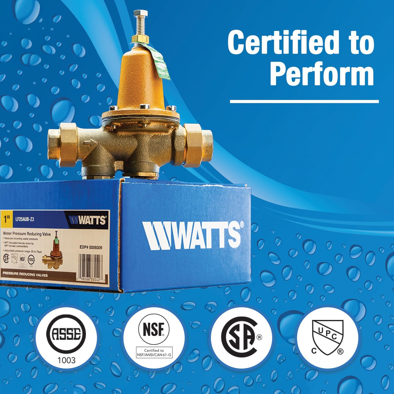
The Watts LF25AUB-Z3 Series 1" Lead-Free Water Pressure Reducing Valve is engineered to safeguard plumbing systems and optimize water consumption in various settings, including commercial, industrial, and residential applications. This standard model effectively reduces incoming water pressure to a manageable, preset level. Its design incorporates a replaceable seat module, NPT threaded female union inlet by NPT female outlet connections, and a bypass feature to manage thermal expansion pressure. The valve is constructed from lead-free cast copper silicon alloy, ensuring compliance with safety standards.
2. Key Features
- Lead-Free Construction: Manufactured from lead-free cast copper silicon alloy, ensuring safe water delivery.
- Pressure Reduction: Reduces incoming water pressure to protect plumbing systems and reduce water consumption.
- Adjustable Pressure Range: Allows for an adjustable pressure range between 25 to 75 psi (172 to 517 kPa), with a factory standard setting at 50 psi (345 kPa).
- High Maximum Operating Pressure: Suitable for pressures up to 300 psi (20.7 bar).
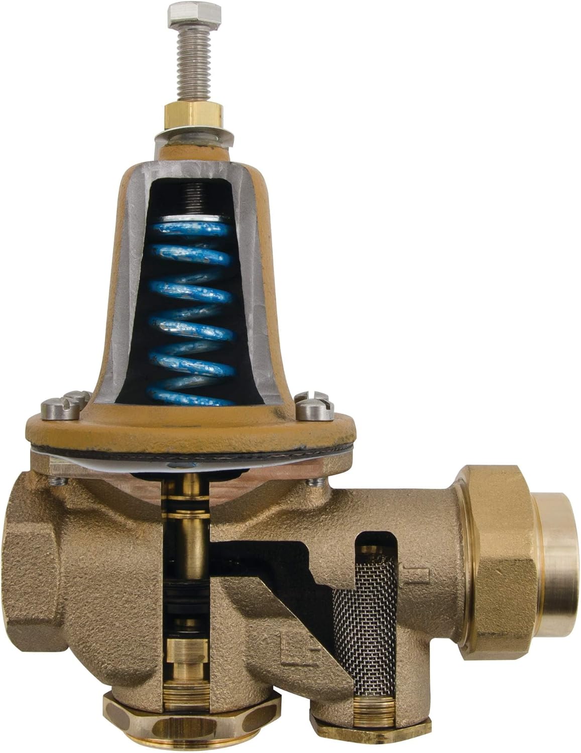
- Thermal Expansion Bypass: Includes a bypass feature to control thermal expansion pressure, allowing water to flow back into the main supply when outlet pressure exceeds main supply pressure due to thermal expansion.
- Wide Temperature Range: Operates effectively within a temperature range of 33°F (0.5°C) to 180°F (82°C).
- Easy Maintenance: Features a replaceable seat module and is designed for straightforward in-line serviceability.
- Durable Components: Includes a removable integral stainless steel strainer, high-temperature diaphragm, and a sealed spring case with stainless steel cage screws for robust performance, even in waterwork pit installations.
- Versatile Connections: NPT threaded female union inlet by NPT female outlet connections simplify installation.
3. Specifications
| Attribute | Value |
|---|---|
| Model Number | LF25AUB-Z3 |
| Size | 1 Inch |
| Material | Lead-Free Cast Copper Silicon Alloy (Brass) |
| Inlet Connection Type | NPT Female Union |
| Outlet Connection Type | NPT Female |
| Adjustable Pressure Range | 25 to 75 psi (172 to 517 kPa) |
| Standard Setting | 50 psi (345 kPa) |
| Maximum Operating Pressure | 300 psi (20.7 bar) |
| Temperature Range | 33°F (0.5°C) to 180°F (82°C) |
| Dimensions (L x W x H) | 3.9 x 7.4 x 8.5 inches |
| Item Weight | 5.05 pounds |
4. Setup and Installation
Proper installation of the Watts LF25AUB-Z3 valve is crucial for optimal performance and longevity. It is recommended that installation be performed by a qualified plumber or technician.
4.1 Pre-Installation Checklist
- Ensure the main water supply is turned off before beginning installation.
- Verify that the installation location is accessible for future maintenance.
- Confirm the valve size (1 inch) matches your plumbing system requirements.
- Gather necessary tools: pipe wrenches, thread sealant (Teflon tape or pipe dope), and a pressure gauge for verification.
4.2 Installation Steps
- Prepare the Pipe: Cut a section of the main water line where the valve is to be installed. Ensure the cut ends are clean and free of burrs.
- Orient the Valve: The valve has an arrow indicating the direction of water flow. Ensure the arrow points in the direction of water flow from the main supply into your home. The NPT female union inlet connects to the incoming water supply, and the NPT female outlet connects to the household plumbing.
- Apply Thread Sealant: Apply an appropriate thread sealant (e.g., Teflon tape or pipe dope) to the male threads of the pipes that will connect to the valve's union and outlet.
- Connect the Valve: Securely connect the valve to the plumbing lines. Use pipe wrenches to tighten connections, but do not overtighten to avoid damaging the valve or pipes.
- Check for Leaks: Slowly turn on the main water supply and carefully inspect all connections for leaks. Tighten any leaking connections as needed.
- Verify Pressure: Use a pressure gauge connected to a nearby hose bib or test port to verify the outlet pressure. The valve comes factory preset to 50 psi.

Image: End Connection Flexibility. The valve supports various connection types for simplified installation.
5. Operating Instructions
The Watts LF25AUB-Z3 valve is designed to maintain a consistent outlet pressure. The factory setting is typically 50 psi, but it can be adjusted within its specified range.
5.1 Adjusting Outlet Pressure
- Locate Adjustment Screw: The pressure adjustment screw is located at the top of the valve, typically covered by a cap or a locknut.
- Loosen Locknut (if present): If there is a locknut, loosen it before making adjustments.
- Adjust Pressure:
- To increase the outlet pressure, turn the adjustment screw clockwise.
- To decrease the outlet pressure, turn the adjustment screw counter-clockwise.
- Monitor Pressure: Use a reliable pressure gauge connected to a downstream hose bib or test port to accurately monitor the pressure as you adjust.
- Tighten Locknut: Once the desired pressure is set (within the 25-75 psi range), tighten the locknut (if present) to secure the setting.
Note: Avoid setting the pressure too high, as excessive pressure can damage household plumbing and appliances. Most residential plumbing is designed for a maximum of 80 psi.
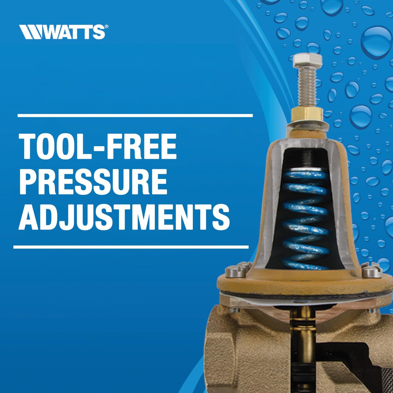
Image: Tool-Free Pressure Adjustments. The valve allows for easy pressure adjustments from the top.
6. Maintenance
Regular maintenance ensures the continued optimal performance and extends the lifespan of your Watts LF25AUB-Z3 valve.
6.1 Routine Checks
- Annual Pressure Check: Periodically check your household water pressure using a pressure gauge to ensure the valve is maintaining the desired setting.
- Leak Inspection: Visually inspect the valve and surrounding connections for any signs of leaks.
- Strainer Cleaning: The valve includes a removable integral stainless steel strainer. If you notice a significant drop in water pressure or flow, the strainer may be clogged and require cleaning. Consult a professional for this procedure if you are unsure.
6.2 Servicing
The valve is designed for easy in-line serviceability, featuring a replaceable seat module. For internal servicing or replacement of components, it is highly recommended to contact a certified plumbing professional. Attempting repairs without proper knowledge and tools can lead to damage or improper function.

Image: Fast & Easy Maintenance. The valve is designed for service directly in line from the top.
7. Troubleshooting
This section provides general guidance for common issues. For complex problems, consult a qualified plumber.
| Problem | Possible Cause | Solution |
|---|---|---|
| High Water Pressure Downstream | Valve setting too high; debris in valve; worn diaphragm/seat. | Adjust pressure setting (Section 5.1); clean strainer; consult professional for internal inspection/repair. |
| Low Water Pressure Downstream | Valve setting too low; clogged strainer; insufficient incoming pressure. | Adjust pressure setting (Section 5.1); clean strainer; check main supply pressure. |
| Water Hammering | Pressure fluctuations; air in pipes; valve malfunction. | Ensure stable pressure setting; bleed air from system; if persistent, consult professional. |
| Valve Leaking | Loose connections; damaged seals/gaskets; internal component failure. | Check and tighten connections; consult professional for seal replacement or internal repair. |
8. Product Images


9. Warranty and Support
For specific warranty information and technical support regarding your Watts LF25AUB-Z3 Water Pressure Reducing Valve, please refer to the official Watts website or contact Watts customer service directly. Keep your purchase receipt as proof of purchase for any warranty claims.
Watts Customer Service: Please visit www.watts.com for contact details and support resources.


