1. Introduction
This manual provides essential information for the safe and efficient installation, operation, and maintenance of the HLTNC HS320 Variable Frequency Drive (VFD) Inverter. The HS320 is designed to control the speed of three-phase AC motors, commonly used in applications such as spindle speed control. Please read this manual thoroughly before using the product to ensure proper functionality and safety.
2. Safety Information
WARNING: Improper installation or operation can lead to serious injury or equipment damage. Always follow safety guidelines.
- Electrical Hazard: Ensure all power is disconnected from the supply before performing any installation, wiring, or maintenance. Wait at least 10 minutes after disconnecting power for capacitors to discharge before touching internal components.
- Grounding: Always ensure the VFD is properly grounded according to local electrical codes.
- Qualified Personnel: Installation and maintenance should only be performed by qualified electrical personnel.
- Environment: Do not operate the VFD in environments with excessive dust, moisture, corrosive gases, or direct sunlight. Mount the inverter on a non-combustible surface.
- Overload Protection: Do not bypass any safety or overload protection features.
Refer to the warning labels on the device for additional safety instructions.

3. Product Overview
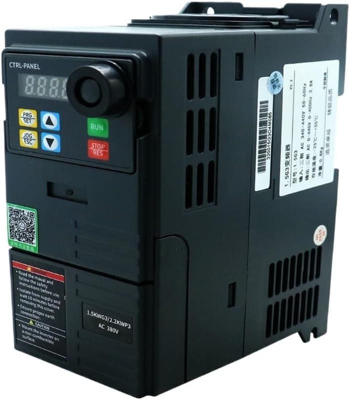
The HLTNC HS320 is a compact Variable Frequency Drive designed for precise motor speed control. It features a digital display, control buttons, and a rotary encoder for parameter adjustment. The unit is equipped with various input/output terminals for external control and monitoring.


4. Specifications
The following table outlines the key technical specifications for the HLTNC HS320 VFD (0.75KW, 380V, 0-400Hz variant).
| Feature | Specification |
|---|---|
| Model Number | HS320 |
| Input Voltage | 380V AC |
| Output Power | 0.75KW |
| Output Phase | 3-Phase |
| Output Frequency Range | 0-400Hz |
| Type | DC/AC Inverter |
| Control Method | Vector Control / V/F Control (refer to detailed parameter settings) |
| Cooling Method | Fan Cooled |
| Operating Temperature | Typically -10°C to 40°C (14°F to 104°F) |
| Humidity | Less than 90% RH, non-condensing |
| Altitude | Below 1000m (3300ft) |
| Protection Level | IP20 (typical for enclosed VFDs) |
| Physical Dimensions & Weight | Refer to product packaging or official documentation for accurate physical dimensions and weight. |
5. Installation
5.1 Mounting
- Mount the VFD vertically on a sturdy, non-combustible surface.
- Ensure adequate ventilation space around the unit (typically 10cm above and below, 5cm on sides) for proper heat dissipation.
- Avoid mounting in direct sunlight, near heat sources, or in areas subject to vibration.
- Use appropriate screws and mounting hardware to secure the VFD firmly.
5.2 Wiring
All wiring must comply with local and national electrical codes. Use appropriate wire gauges for the VFD's power rating.
5.2.1 Power Input (R, S, T)
- Connect the 380V AC three-phase power supply to the R, S, and T terminals.
- Install an appropriate circuit breaker or fuse upstream for protection.
5.2.2 Motor Output (U, V, W)
- Connect the three-phase motor to the U, V, and W output terminals.
- Ensure the motor's rated voltage and current are compatible with the VFD.
5.2.3 Grounding (PE)
- Connect the VFD's grounding terminal (PE) to a reliable earth ground. This is critical for safety and EMI reduction.
5.2.4 Control Terminals
The VFD provides various control terminals for external start/stop, speed reference (analog input), multi-function inputs, and relay outputs. Refer to the detailed wiring diagram in the full product manual for specific terminal assignments and functions. Common connections include:
- Analog Input: For external speed control via potentiometer or 0-10V/4-20mA signal.
- Digital Inputs: For external start, stop, forward/reverse, multi-step speed commands.
- Relay Outputs: For fault indication or run status.
6. Operation
6.1 Control Panel Functions
The integrated control panel allows for direct operation and parameter setting.
- Digital Display: Shows frequency, output current, voltage, and parameter codes.
- RUN Button: Starts the motor.
- STOP/RES Button: Stops the motor or resets a fault.
- PRG/SET Button: Enters/exits parameter setting mode, confirms parameter changes.
- JOG/ESC Button: Initiates JOG operation (momentary run) or exits a menu without saving.
- Up/Down Arrows: Navigate through parameters or adjust values.
6.2 Basic Operation Steps
- Power On: Apply power to the VFD. The display will light up.
- Set Frequency: Use the Up/Down arrows to set the desired output frequency.
- Start Motor: Press the RUN button. The motor will accelerate to the set frequency.
- Stop Motor: Press the STOP/RES button. The motor will decelerate and stop.
7. Parameter Settings
The HLTNC HS320 VFD has a comprehensive set of parameters to customize its operation. Accessing and modifying these parameters allows fine-tuning for specific applications.
7.1 Entering Parameter Mode
- Press the PRG/SET button to enter parameter setting mode. The display will show a parameter group code (e.g., P00).
- Use the Up/Down arrows to navigate through parameter groups (e.g., P00, P01, P02, etc.).
- Press PRG/SET again to enter a specific parameter within a group (e.g., P00.01).
7.2 Modifying Parameters
- Once a specific parameter is selected, use the Up/Down arrows to change its value.
- Press PRG/SET to save the new value. The display may flash to confirm.
- Press JOG/ESC to exit the current parameter or group without saving changes.
7.3 Important Parameters (Examples)
- P00.01 (Max Output Frequency): Sets the maximum frequency the VFD can output.
- P00.03 (Acceleration Time): Defines the time it takes for the motor to accelerate from 0Hz to the maximum frequency.
- P00.04 (Deceleration Time): Defines the time it takes for the motor to decelerate from the maximum frequency to 0Hz.
- P00.05 (Rated Motor Frequency): Set to the motor's nominal frequency.
- P00.06 (Rated Motor Voltage): Set to the motor's nominal voltage.
- P00.07 (Rated Motor Current): Set to the motor's nominal current.
For a complete list of parameters and their detailed descriptions, refer to the comprehensive parameter manual provided with your HLTNC HS320 VFD.
8. Maintenance
Regular maintenance ensures the longevity and reliable operation of your VFD.
- Cleaning: Periodically clean the VFD's exterior and cooling fins to prevent dust accumulation, which can hinder heat dissipation. Use a soft, dry cloth. Do not use liquids or solvents.
- Fan Inspection: Check the cooling fan for proper operation and ensure it is free from obstructions. Replace if noisy or not functioning.
- Terminal Tightness: Periodically check all wiring terminals for tightness. Loose connections can cause overheating and intermittent operation.
- Environmental Check: Ensure the operating environment remains within specified temperature and humidity ranges.
9. Troubleshooting
This section provides solutions for common issues. For complex problems, contact technical support.
| Problem/Error Code | Possible Cause | Solution |
|---|---|---|
| No Display/Power | No input power; Blown fuse; Internal fault. | Check power supply and fuses. If power is present, contact support. |
| Motor Not Running | VFD not in RUN mode; Incorrect frequency setting; Motor wiring issue; Fault condition. | Press RUN. Check frequency setting. Verify motor wiring. Check for fault codes. |
| Overcurrent Fault (OC) | Motor overload; Short circuit in motor wiring; Rapid acceleration/deceleration. | Reduce load. Check motor wiring. Increase acceleration/deceleration times (P00.03/P00.04). |
| Overvoltage Fault (OV) | Regenerative braking from motor; High input voltage. | Increase deceleration time. Check input voltage. Consider braking resistor if needed. |
| Undervoltage Fault (UV) | Low input voltage; Power sag. | Check input power supply voltage. |
| Overheat Fault (OH) | Insufficient ventilation; High ambient temperature; Clogged fan. | Ensure proper ventilation. Clean cooling fins and fan. Reduce ambient temperature. |
Always press the STOP/RES button to clear a fault after addressing the cause.
10. Warranty and Support
For warranty information, technical support, or service inquiries, please refer to the documentation provided with your purchase or contact your vendor. Ensure you have your product model number (HS320) and purchase details available when seeking support.


