1. Introduction
This manual provides comprehensive instructions for the PDDAXLQUE DX-LR03 433/475MHz RF LoRa Module. It covers product features, setup procedures, operating instructions, and technical specifications to ensure proper use and optimal performance of the module. The DX-LR03 is designed for ultra-long distance LoRa communication, offering robust and reliable data transmission.
2. Product Overview
2.1 Key Features
- Ultra-Long Distance Communication: Achieves transmission distances up to 10KM in open visibility.
- Frequency Band: Supports 433/475MHz communication.
- High Transmission Power: Features a PA amplifier with up to 30dBm transmission power.
- ASR6601 SOC Chip: Integrated ASR6601 System-on-Chip for efficient operation.
- UART Serial Port: Facilitates transparent data transmission via UART serial communication.
- AT Command Set: Configurable through a comprehensive set of AT commands for various parameters.
- Wide Baud Rate Support: Supports baud rates from 1200 to 128000 bps (Default: 9600bps/8/n/1).
- Certifications: CE, FCC, and ROSH certified for safety and reliability.
- Robust Design: Equipped with an RF shielding cover, offering strong anti-interference, anti-static, and EMC electromagnetic compatibility.
- External Antenna Support: Designed for use with external antennas.

Figure 1: DX-LR03 Module Key Features and Dimensions. This image highlights the ASR6601 SOC chip, UART serial communication, frequency support, output power, receiver sensitivity, operating voltage, module size, and certifications. It also shows the module dimensions and antenna length.
2.2 Main Parameters
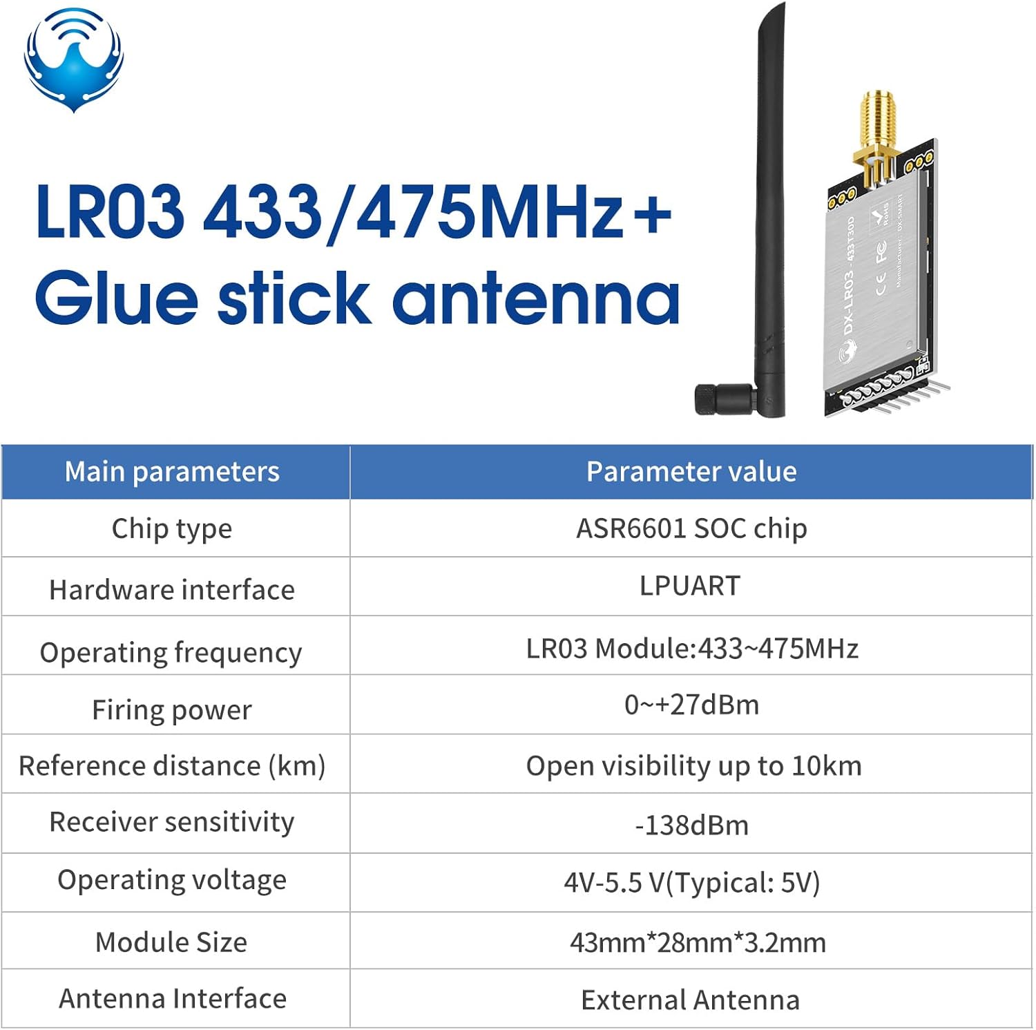
Figure 2: Main Parameters of the DX-LR03 Module. This table details the chip type (ASR6601 SOC), hardware interface (LPUART), operating frequency (433-475MHz), firing power (0~+27dBm), reference distance (up to 10km), receiver sensitivity (-138dBm), operating voltage (4V-5.5V), module size (43mm*28mm*3.2mm), and antenna interface (External Antenna).
3. Setup and Installation
3.1 Module Components

Figure 3: DX-LR03 LoRa Module with an attached antenna. This image shows the compact module with its pin headers and the external antenna connected via an SMA connector.
3.2 Pinout and Connections
The DX-LR03 module features a standard pinout for easy integration. Ensure correct voltage supply and serial communication connections.

Figure 4: DX-LR03 Module Pinout and Interface Details. This image illustrates the traceability ID, indicator light, VCC (3.3-5.5V), GND, AUX (Module RF status indicator pin), M1, M0, RXD, TXD, and the antenna interface. It also shows the module's serial number and certifications.
3.3 Connecting with a USB to TTL Adapter
For initial setup and testing, a USB to TTL adapter can be used to interface the module with a computer. Connect the module's TXD to the adapter's RXD, and the module's RXD to the adapter's TXD. Ensure common ground (GND) and proper power supply (VCC).

Figure 5: USB to TTL Adapter and Wiring Diagram. This image shows a USB to TTL module adapter board and a wiring diagram illustrating how to connect the DX-LR03 module to it for serial communication, indicating connections for VCC, GND, TXD, RXD, M1, M0, and AUX.
4. Operating Instructions
4.1 Serial Communication
The DX-LR03 module uses UART serial communication for transparent data transmission. The default baud rate is 9600bps with 8 data bits, no parity, and 1 stop bit (9600/8/N/1). Other supported baud rates include 1200, 2400, 19200, 38400, 57600, 115200, and 128000 bps.
4.2 AT Command Settings
The module's operating parameters can be configured using AT commands. These commands allow setting and querying various aspects such as operating mode, frequency, MAC address, bandwidth, spreading factor, coding rate, and transmission power. Refer to the detailed AT command set documentation for a complete list of commands and their usage.

Figure 6: Overview of AT Commands. This image shows a partial AT command table with examples like AT (test), +++ (enter/exit AT command mode), AT+BAUD (set/query baud rate), AT+MAC (set/query device address), AT+MODE (set/query operating mode), AT+SLEEP (set/query power consumption mode), AT+CHANNEL (set/query working channels), and AT+POWE (set/query transmit power).
4.3 Communication Modes
The DX-LR03 module supports different communication modes, including fixed-point transmission and broadcast transmission.
- Fixed-point transmission: Data is sent to a specific module identified by its MAC address and channel.
- Broadcast transmission: Data is sent to all modules within range on a specified channel, without requiring a specific MAC address.

Figure 7: Fixed-point and Broadcast Transmission Modes. This diagram illustrates how data is transmitted in both fixed-point (requiring matching MAC and Channel) and broadcast (requiring only matching Channel) modes, showing successful and unsuccessful data reception scenarios.
5. Troubleshooting
- No Communication: Verify power supply, serial port connections (TX/RX cross-over), and baud rate settings. Ensure both modules are configured to the same frequency and communication parameters.
- Limited Range: Check antenna connection and placement. Ensure there are no significant obstructions between modules. Verify transmission power settings.
- Module Not Responding to AT Commands: Ensure the module is in AT command mode (usually by sending '+++' or specific entry sequence). Check serial port settings.
- Interference Issues: Ensure the module is properly shielded and away from strong electromagnetic interference sources.
6. Technical Specifications
| Parameter | Value |
|---|---|
| Model Number | LR03-433/475Mhz |
| Brand | PDDAXLQUE |
| Chip Type | ASR6601 SOC |
| Operating Frequency | 433/475MHz |
| Transmission Power | 0 ~ +30dBm (with PA amplifier) |
| Receiver Sensitivity | -138dBm |
| Communication Distance | Up to 10KM (line-of-sight) |
| Data Interface | UART Serial Port |
| Baud Rates | 1200, 2400, 9600 (default), 19200, 38400, 57600, 115200, 128000 bps |
| Operating Voltage | 4V - 5.5V (Typical: 5V) |
| Module Dimensions | 43mm (L) x 28mm (W) x 3.2mm (H) |
| Antenna Interface | External Antenna |
| Certifications | CE, FCC, ROSH |
| Manufacturer | DX-SMART |
7. Support and Documentation
PDDAXLQUE provides comprehensive technical support and documentation for the DX-LR03 module. This includes detailed technical documentation, AT command sets, module footprints, reference design schematics, and development/test tools. For further assistance or to access additional resources, please refer to the official product documentation.
For technical inquiries or support, please contact the manufacturer through the provided channels in the product documentation or the seller's support information.