1. Introduction
The ANJIELO SMART Wireless Bridge 68066 is designed to provide extended network coverage for various outdoor applications. This 2.4G Point-to-Point (PtP) and Point-to-Multi-Point (PtMP) outdoor WiFi bridge offers long-range connectivity up to 1KM, making it suitable for connecting distant buildings, barns, shops, farms, garages, warehouses, or security cameras. It features a high-gain antenna, dual 100Mbps Ethernet ports, and a convenient Type-C power supply.

Image 1.1: ANJIELO SMART Wireless Bridge units demonstrating long-range point-to-point connectivity.
2. Package Contents
Please verify that all items are present in your package:
- 2 x Wireless Bridge Units
- 2 x Type-C Adapters
- 2 x Chargers
3. Product Overview and Features
The ANJIELO SMART Wireless Bridge is engineered for robust and reliable outdoor network extension. Key features include:
- Extended Network Coverage: Achieves a range of up to 1KM, ideal for connecting remote locations.
- Dual 100Mbps Ethernet Ports: Provides two high-speed LAN ports for seamless integration with various network devices.
- Type-C Power Supply: Offers convenient power options, compatible with power banks and portable chargers.
- Advanced High-Gain Antenna: Ensures strong directional signal transmission and reception for optimal long-range performance.
- Plug-and-Play Setup: Pre-configured for one-to-one pairing, simplifying installation without complex UI configuration.
- High-Speed Data Transmission: Operates on the 2.4GHz band, delivering speeds up to 100Mbps for stable connectivity.
- Superior Wall Penetration: Designed to maintain signal integrity through obstacles.
- Rugged Outdoor Design: IP65-rated housing provides waterproof, dustproof, and weather-resistant protection.

Image 3.1: Overview of the Wireless Bridge's capabilities.
4. Setup Instructions
The ANJIELO SMART Wireless Bridge is designed for a straightforward plug-and-play setup, with units pre-configured for one-to-one pairing.
4.1. Physical Connection
- Attach Antennas: Screw the provided antennas onto the SMA connectors on each wireless bridge unit. Ensure they are securely fastened.
- Power Connection: Connect the Type-C adapter to the Type-C port on each bridge unit, then plug the charger into a power outlet.
- Ethernet Connection (Transmitter Unit): Connect one Ethernet port of the first bridge unit (transmitter) to your router or network switch using an Ethernet cable. This unit will receive the internet signal.
- Ethernet Connection (Receiver Unit): Connect one Ethernet port of the second bridge unit (receiver) to your target device (e.g., IP camera, NVR, computer, switch) using an Ethernet cable. This unit will provide the extended network connection.

Image 4.1.1: Attaching the antenna to the bridge unit.
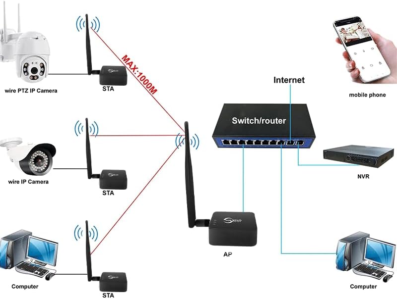
Image 4.1.2: Connecting the Type-C power supply.

Image 4.1.3: Connecting the transmitter unit to a router.
4.2. Automatic Pairing
The units are pre-configured for automatic connection. Once both units are powered on and within range, they will establish a wireless bridge link automatically. No manual configuration through a user interface is typically required for a basic point-to-point setup.

Image 4.2.1: Example of automatic connection for an IP camera setup.

Image 4.2.2: Illustration of avoiding complex wiring using wireless bridges.
5. Operating Instructions
Once the wireless bridge units are set up and powered, they will automatically form a wireless link, extending your network to the remote location.
5.1. Point-to-Point (PtP) Operation
In a Point-to-Point setup, two bridge units communicate directly with each other to extend a single network connection over a long distance. One unit acts as the Access Point (AP) and the other as the Station (STA).
- The AP unit connects to your main network (router/switch).
- The STA unit connects to your remote device(s).
- The wireless link between them provides the network extension.

Image 5.1.1: Wireless long-range transmission between two locations.
5.2. Point-to-Multi-Point (PtMP) Operation
For Point-to-Multi-Point scenarios, one bridge unit acts as the central Access Point (AP), and multiple other bridge units act as Stations (STAs), connecting various remote devices to the central network.
- One AP unit connects to your main network.
- Multiple STA units are deployed at different remote locations, each connecting to a device or local network.
- The AP broadcasts the network to all connected STA units.

Image 5.2.1: Connecting multiple devices in a PtMP configuration.
5.3. Applicable Scenarios
This wireless bridge is ideal for situations where running long network cables is impractical or costly. Common applications include:
- Extending internet to a detached garage or workshop.
- Connecting IP cameras for surveillance in large properties or farms.
- Providing network access to remote offices or buildings.
- Establishing network links for outdoor events or temporary setups.

Image 5.3.1: Various application scenarios for the wireless bridge.
6. Maintenance
To ensure optimal performance and longevity of your ANJIELO SMART Wireless Bridge, follow these maintenance guidelines:
- Keep Clean: Periodically wipe the exterior of the units with a soft, dry cloth to remove dust and dirt. Do not use liquid cleaners or solvents.
- Antenna Check: Ensure antennas remain securely attached and are not damaged.
- Cable Integrity: Regularly inspect Ethernet and power cables for any signs of wear or damage. Replace damaged cables immediately.
- Environmental Protection: Although IP65-rated, avoid prolonged exposure to extreme weather conditions if possible. Ensure proper mounting to prevent water accumulation.
- Firmware Updates: Check the manufacturer's website periodically for any available firmware updates to improve performance and security.
7. Troubleshooting
If you encounter issues with your wireless bridge, refer to the following troubleshooting steps:
- No Power:
- Ensure the Type-C adapter is securely connected to the bridge unit and the charger is plugged into a working power outlet.
- Verify the power outlet is functional by plugging in another device.
- No Wireless Link:
- Ensure both bridge units are powered on and their status indicators are active.
- Check that the units are within the specified operating range (up to 1KM) and have a clear line of sight if possible. Obstacles can degrade signal quality.
- Restart both bridge units by unplugging and replugging their power.
- No Internet/Network Access at Remote End:
- Verify that the transmitter unit is correctly connected to your main router/network and that the main network has internet access.
- Check the Ethernet cable connection between the receiver unit and your remote device.
- Ensure the remote device's network settings are configured for automatic IP address (DHCP).
- Slow Connection Speed:
- Check for potential interference sources (e.g., other 2.4GHz devices, thick walls).
- Ensure the units have a clear line of sight. Repositioning them slightly can sometimes improve performance.
- Verify that the Ethernet cables used are Cat5e or Cat6 for optimal performance.
8. Specifications
| Feature | Specification |
|---|---|
| Brand | ANJIELO SMART |
| Model Number | 68066 |
| Product Dimensions | 2.5 x 2.5 x 1 inches (6.35 x 6.35 x 2.54 cm) |
| Item Weight | 1 pound (0.45 kg) |
| Color | Black |
| Data Link Protocol | IEEE 802.11ah |
| Data Transfer Rate | Up to 100 Mbps (2.4GHz band) |
| Wireless Frequency | 2.4 GHz |
| Ethernet Ports | 2 x 10/100 Mbps RJ45 |
| Power Supply | Type-C |
| Outdoor Rating | IP65 (Waterproof, Dustproof, Weather-resistant) |
| Compatible Devices | Desktop, Printer, Security Camera, NVR, etc. |
| Compatible OS Family | Linux, Windows |

Image 8.1: Product dimensions.
9. Warranty and Support
For warranty information and technical support, please refer to the documentation provided with your purchase or contact ANJIELO SMART customer service through the retailer where the product was purchased. Keep your proof of purchase for warranty claims.


