Introduction
This manual provides comprehensive instructions for the installation, operation, maintenance, and troubleshooting of the IOAUOVEG Logic Board Inverter, designed as a replacement network motherboard for various Xiaomi TV models. This specific model features a small interface configuration, compatible with models such as L32M5-5ASP, L32M5-5ARU, L32M6-6ARG, and L32M6-6AEU. Please read this manual carefully before attempting any installation or repair to ensure proper function and safety.
Safety Information
- Professional Installation Recommended: Installation of this component requires technical expertise and familiarity with TV electronics. If you are not confident in your abilities, seek assistance from a qualified technician.
- Disconnect Power: Always disconnect the TV from the main power supply before beginning any installation or repair work. Failure to do so can result in electric shock or damage to the TV.
- Electrostatic Discharge (ESD) Precautions: Electronic components are sensitive to static electricity. Wear an anti-static wrist strap and work on an anti-static mat to prevent damage to the motherboard and other TV components.
- Handle with Care: Avoid touching the integrated circuits and connectors directly. Hold the board by its edges.
- Verify Compatibility: Ensure this motherboard is the correct replacement part for your specific TV model and interface type (small interface). Incorrect parts can cause damage.
- Observe Polarity: When connecting cables, pay close attention to their orientation and polarity to avoid damage.
Components Overview
The IOAUOVEG Logic Board Inverter is a complex circuit board containing various components essential for the TV's operation, including the main processor, memory, power management circuits, and input/output interfaces. Below are images illustrating the general layout and key connection points of the motherboard.

Figure 1: Top-down view of the IOAUOVEG Logic Board Inverter. This image displays the overall layout of the circuit board, highlighting the main components such as the heat sink, various capacitors, inductors, and multiple input/output ports including HDMI, USB, and network (Ethernet) connectors. The power supply section is visible on the left side.
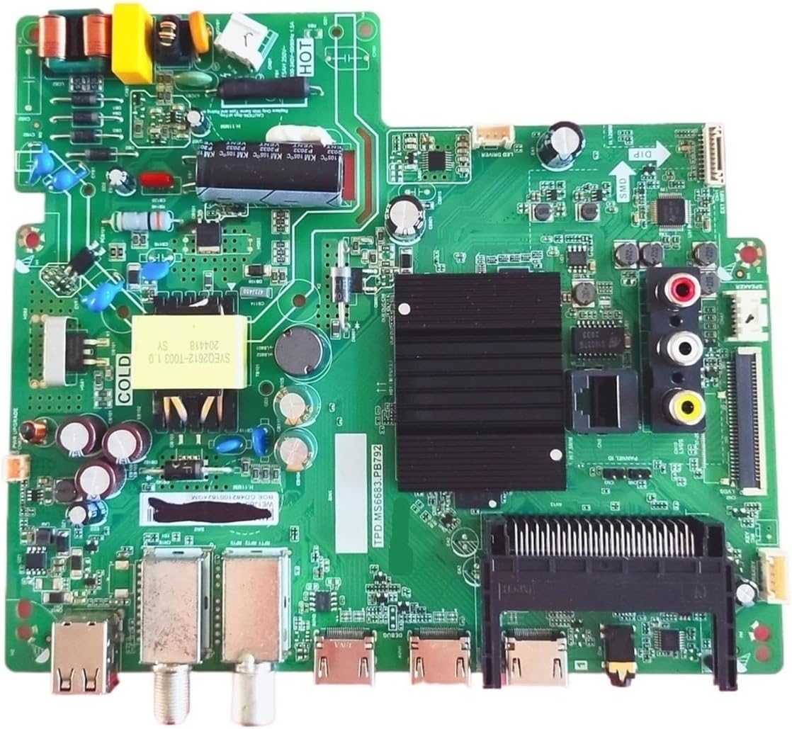
Figure 2: Alternative top-down view of the IOAUOVEG Logic Board Inverter. This perspective provides a clearer look at the various ports and connectors, including the coaxial input, additional USB ports, and the main ribbon cable connector for the display panel. The heat sink for the main processor is centrally located.

Figure 3: Close-up of the IOAUOVEG Logic Board Inverter, emphasizing the small interface connector. A red arrow points to a specific ribbon cable connector, which is crucial for connecting to the TV's display panel or other internal components. This highlights the "small interface" characteristic of this particular board variant.
Setup and Installation
This section outlines the general steps for replacing a TV motherboard. Due to variations in TV models, specific disassembly and reassembly procedures may differ. Always refer to your TV's service manual if available.
Required Tools:
- Screwdriver set (Phillips, Torx)
- Anti-static wrist strap and mat
- Plastic prying tools (optional, for opening TV casing)
- Clean, well-lit workspace
Installation Steps:
- Prepare the TV: Disconnect the TV from all power sources and external devices. Place the TV face down on a soft, clean surface to protect the screen.
- Remove Back Cover: Carefully remove all screws securing the TV's back cover. Use plastic prying tools if necessary to gently separate the cover from the chassis.
- Locate Old Motherboard: Identify the existing motherboard. It is typically the largest circuit board and has most of the external ports.
- Disconnect Cables: Systematically disconnect all cables connected to the old motherboard. This includes power cables, ribbon cables (LVDS, T-CON), speaker cables, and input/output cables. Take photos or make notes of cable connections for easier reassembly.
- Remove Old Motherboard: Unscrew the old motherboard from the TV chassis and carefully lift it out.
- Install New Motherboard: Place the new IOAUOVEG Logic Board Inverter into position, ensuring it aligns with the screw holes. Secure it with the screws previously removed.
- Reconnect Cables: Reconnect all cables to the new motherboard, referring to your notes or photos. Pay special attention to the orientation of ribbon cables, especially the small interface connector (refer to Figure 3). Ensure all connections are firm and secure.
- Initial Test (Optional but Recommended): Before fully reassembling the TV, you may perform a preliminary power-on test. Connect the TV to power and check if it powers on and displays an image. If successful, disconnect power again.
- Reassemble TV: Carefully replace the back cover and secure it with all screws.
- Final Test: Connect the TV to power and all necessary external devices. Power on the TV and verify all functions (picture, sound, network, inputs) are working correctly.
Operating Instructions
Once the IOAUOVEG Logic Board Inverter is correctly installed, the TV should function as intended. This motherboard is a core component that enables the TV's overall operation. There are no specific "operating instructions" for the motherboard itself, as its function is integrated into the TV's system. Refer to your Xiaomi TV's original user manual for instructions on how to operate your television, including navigating menus, connecting to networks, and using various input sources.
The new motherboard ensures:
- Fast Response Speed: The TV should respond quickly and stably to various operations.
- Stable Picture Quality: Consistent and clear image display.
- Energy Efficiency: Optimized power conversion for reduced energy consumption.
Maintenance
The IOAUOVEG Logic Board Inverter is designed for long-term reliability and typically requires no routine maintenance once installed. However, general care for your television can help prolong the life of all its components, including the motherboard.
- Keep Clean: Ensure the TV's ventilation openings are free from dust and debris to prevent overheating. Use a soft, dry cloth to clean the exterior of the TV. Do not use liquid cleaners directly on the TV or its vents.
- Avoid Extreme Conditions: Do not expose the TV to extreme temperatures, high humidity, or direct sunlight.
- Stable Power Supply: Use a surge protector to protect the TV from power fluctuations and surges.
- Professional Service: If the TV requires internal cleaning or service, always consult a qualified technician.
Troubleshooting
If you encounter issues after installing the new motherboard, consider the following troubleshooting steps:
| Problem | Possible Cause | Solution |
|---|---|---|
| TV does not power on. | Power cable not connected properly, faulty power supply unit (PSU), or motherboard not seated correctly. | Ensure power cable is fully inserted. Check if the TV's power indicator light is on. Re-check all power connections to the motherboard. Verify the PSU is functioning. |
| No picture, but sound is present. | LVDS cable (display ribbon cable) not connected correctly, T-CON board issue, or backlight issue. | Carefully re-seat the LVDS cable (the main ribbon cable connecting the motherboard to the display panel). Ensure the small interface connector (Figure 3) is secure. |
| No sound, but picture is present. | Speaker cables disconnected or faulty speakers. | Check speaker cable connections to the motherboard. Test with external speakers or headphones if possible. |
| Incorrect or distorted picture. | LVDS cable issue, incorrect panel settings (rare for replacement boards), or damaged display panel. | Re-seat the LVDS cable. Ensure the motherboard is compatible with your specific TV panel. |
| Network (Wi-Fi/Ethernet) not working. | Network module not connected or faulty, incorrect TV settings. | Check internal network cable connections. Verify network settings in the TV's menu. |
| TV restarts unexpectedly. | Overheating, unstable power, or a faulty component on the motherboard. | Ensure adequate ventilation. Check power supply stability. If the issue persists, the board may be faulty. |
If these steps do not resolve the issue, it is recommended to consult a professional TV repair technician or contact customer support.
Specifications
- Model Compatibility: Xiaomi TV L32M5-5ASP, L32M5-5ARU, L32M6-6ARG, L32M6-6AEU (and similar models using TPD.MS6683.PB792/PB791 with small interface)
- Part Number: TPD.MS6683.PB792, TPD.MS6683.PB791
- Interface Type: Small interface
- Package Dimensions: 0.39 x 0.39 x 0.39 inches (approximate)
- Item Weight: 1.76 ounces
- Manufacturer: angfan
- Assembly Required: No (component replacement)
- Number of Pieces: 1
Warranty Information
Specific warranty terms for this replacement part may vary depending on the retailer and region of purchase. Please retain your proof of purchase. In case of a defect, contact the seller or manufacturer directly for warranty claims. Typically, electronic replacement parts come with a limited warranty covering manufacturing defects for a specified period from the date of purchase.
Customer Support
For further assistance, technical support, or inquiries regarding this product, please contact the seller or manufacturer, IOAUOVEG, through the platform where the purchase was made. When contacting support, please have your product model number (TPD.MS6683.PB792 / TPD.MS6683.PB791 Small Interface) and proof of purchase readily available.


