Introduction
This user manual provides comprehensive instructions for the Chieftec AS-02B-TG-OP Midi Tower PC Case. It covers essential information regarding product features, installation procedures, operational guidelines, maintenance tips, and technical specifications. Please read this manual thoroughly before installing or operating your PC case to ensure proper functionality and longevity.
Product Overview
The Chieftec AS-02B-TG-OP is a Midi Tower PC case designed for optimal cooling and a modern aesthetic. It features a sleek brushed front panel, a tempered glass side panel, and a pre-installed 120mm PWM fan for efficient heat dissipation.
Key Features:
- Sleek brushed front panel design.
- Tempered glass side panel for component visibility.
- Optimized interior layout for efficient cooling.
- Pre-installed 120mm PWM fan at the rear.
- Support for various motherboard form factors (ATX, micro ATX, Mini-ITX).
- Multiple expansion bays for storage devices.
- Front I/O panel with USB 2.0, USB Type-C, and audio ports.
Component Identification:

Figure 1: Front-left view of the Chieftec AS-02B-TG-OP PC case, showcasing the brushed front panel and the tempered glass side panel.

Figure 2: Direct front view of the Chieftec AS-02B-TG-OP PC case, highlighting the brushed finish of the front panel.

Figure 3: Front-right angle view of the Chieftec AS-02B-TG-OP PC case, showing the subtle design elements.
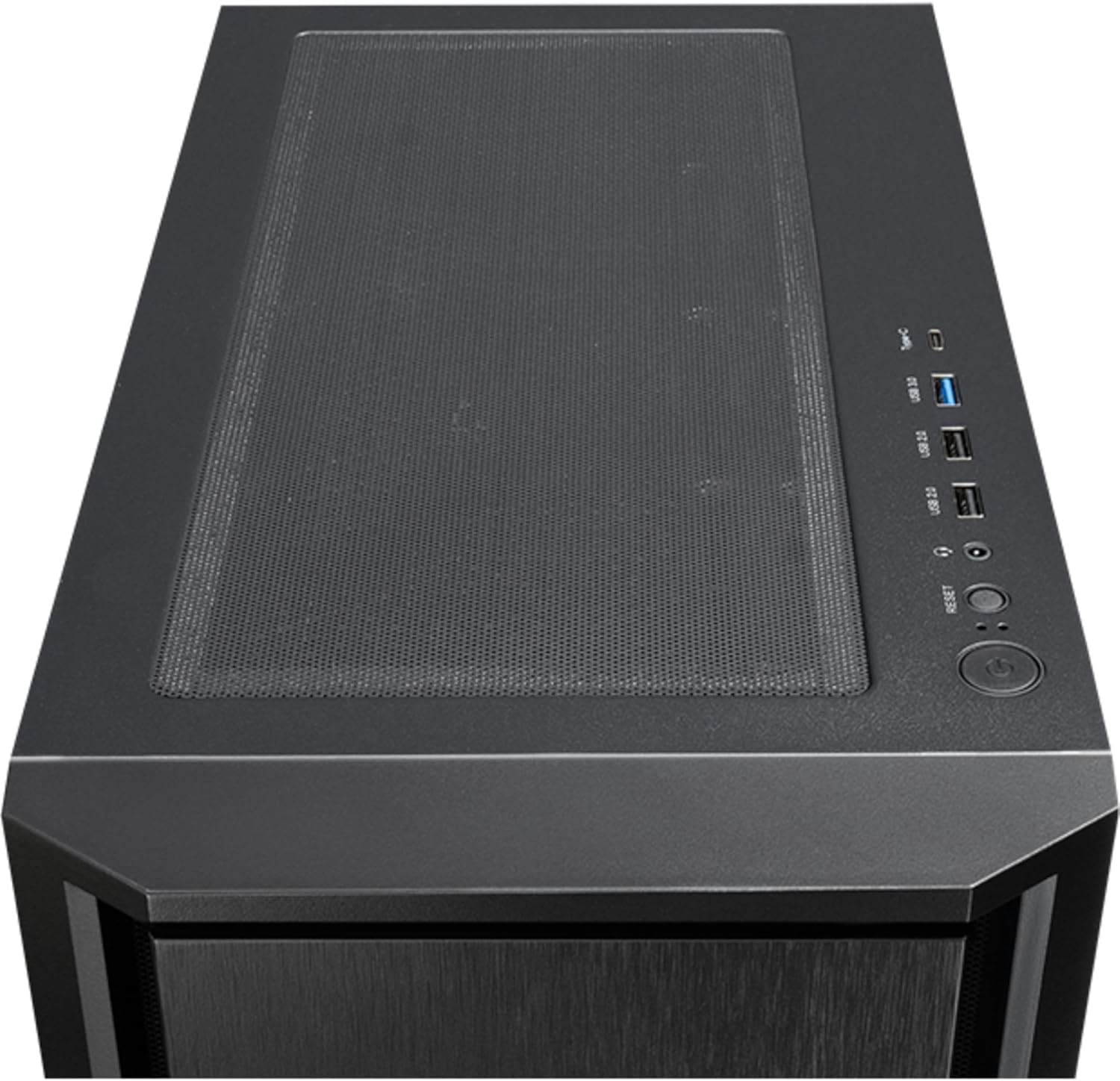
Figure 4: Top view of the Chieftec AS-02B-TG-OP PC case, showing the top ventilation and the front I/O panel with USB ports and audio jacks.

Figure 5: Rear view of the Chieftec AS-02B-TG-OP PC case, detailing the expansion slots, rear fan mount, and PSU opening.

Figure 6: Bottom view of the Chieftec AS-02B-TG-OP PC case, showing the case feet and bottom dust filter area.
Setup and Installation
This section guides you through the process of installing components into your Chieftec AS-02B-TG-OP PC case.
1. Preparing the Case:
- Place the case on a stable, flat surface.
- Carefully remove the tempered glass side panel by unscrewing the thumb screws at the rear.
- Remove the opposite side panel to access the cable management area.
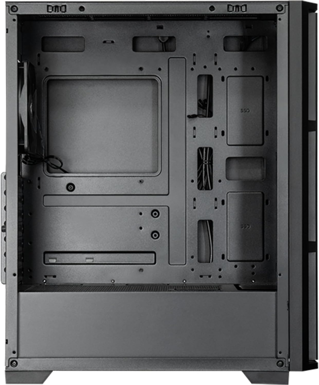
Figure 7: Interior view of the main compartment, showing the motherboard tray and fan mounting points.
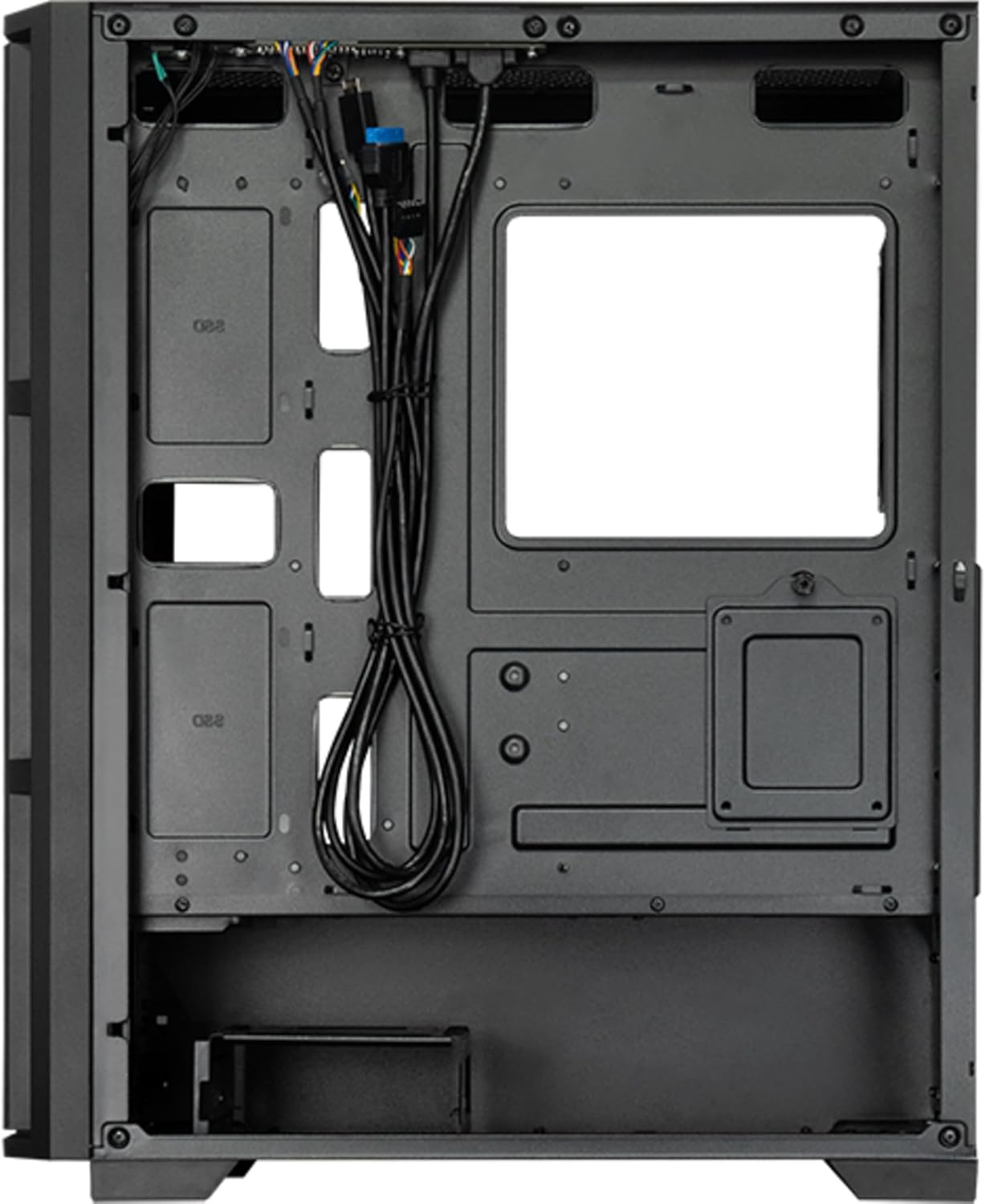
Figure 8: Interior view from the backside, illustrating the cable management routes and drive mounting locations.
2. Motherboard Installation:
- Install the I/O shield into the rear opening of the case.
- Align your ATX, micro ATX, or Mini-ITX motherboard with the standoffs inside the case.
- Secure the motherboard using the provided screws.
3. Power Supply Unit (PSU) Installation:
- The PSU is not included. Install your ATX power supply into the dedicated compartment at the bottom rear of the case.
- Secure the PSU with screws from the rear of the case.
4. Storage Drive Installation:
- Install 3.5" HDDs into the drive cages located at the bottom.
- Install 2.5" SSDs/HDDs into the dedicated mounting points behind the motherboard tray.
- Secure all drives with appropriate screws.
5. Graphics Card and Expansion Cards:
- Remove the necessary expansion slot covers at the rear of the case.
- Insert your graphics card or other expansion cards into the PCIe slots on the motherboard.
- Secure the cards with screws.
6. Cable Management:
- Route all power and data cables through the cutouts and tie-down points behind the motherboard tray.
- Connect the front panel I/O cables (USB, audio, power switch, reset switch, LED indicators) to the corresponding headers on your motherboard.
- Ensure cables do not obstruct airflow.
7. Fan and Cooling System Installation:
- The case includes one pre-installed 120mm PWM fan at the rear.
- Additional fans can be installed at the front (up to 3x 120mm/140mm) and top (up to 2x 120mm/140mm).
- Radiators up to 360mm can be installed at the front and up to 280mm at the top.
- Connect fan power cables to the motherboard fan headers.
Operating Instructions
Once all components are installed and secured, and the side panels are reattached, your PC is ready for operation.
Powering On:
- Connect the power cable from your power supply to a wall outlet.
- Press the power button located on the top I/O panel of the case.
- The system should boot up, and any installed lighting will illuminate.
Front I/O Panel Usage:
- USB 2.0 Ports (x2): For connecting peripherals such as keyboards, mice, and USB drives.
- USB Type-C Port (x1): For connecting modern USB-C devices.
- Audio Jacks (Headphone/Microphone): For connecting headphones, speakers, or microphones.
- Reset Button: To restart the computer.
Maintenance
Regular maintenance helps ensure optimal performance and extends the lifespan of your PC components.
Cleaning:
- Exterior: Use a soft, damp cloth to wipe down the exterior surfaces. Avoid abrasive cleaners.
- Dust Filters: The case features dust filters (e.g., on the top and bottom). Regularly remove and clean these filters with compressed air or by rinsing with water (ensure they are completely dry before reinstallation).
- Interior: Periodically use compressed air to remove dust buildup from fans, heatsinks, and other internal components. Ensure the system is powered off and unplugged before cleaning the interior.
Airflow:
- Ensure adequate space around the case for proper airflow.
- Avoid blocking ventilation openings.
Troubleshooting
This section addresses common issues you might encounter.
No Power:
- Check if the power cable is securely connected to both the PSU and the wall outlet.
- Ensure the power switch on the PSU itself is in the "ON" position.
- Verify that the front panel power switch cable is correctly connected to the motherboard header.
Fans Not Spinning:
- Check if fan power cables are securely connected to the motherboard fan headers or a fan controller.
- Ensure fan speed settings in BIOS/UEFI or operating system are not set to zero RPM.
Front Panel USB/Audio Not Working:
- Verify that the USB and audio cables from the front panel are correctly connected to the corresponding headers on the motherboard.
- Check motherboard drivers for USB and audio functionality.
Specifications
| Feature | Detail |
|---|---|
| Model Name | AS-02B-TG-OP |
| Brand | Chieftec |
| Form Factor | Midi Tower |
| Product Color | Black |
| Supported Motherboard Form Factors | ATX, micro ATX, Mini-ITX |
| Dimensions (W x D x H) | 215 mm x 390 mm x 485 mm (8.46" x 15.35" x 19.09") |
| Item Weight | 5.3 kg (approx. 11.68 lbs) |
| 3.5" Expansion Bays | 2 |
| 2.5" Expansion Bays | 2 |
| 5.25" Expansion Bays | 0 |
| Expansion Slots | 7 |
| Side Window | Yes (Tempered Glass) |
| Lighting | Yes (Multi-color) |
| Max CPU Cooler Height | 16.5 cm |
| Front I/O Ports | 2x USB 2.0, 1x USB Type-C, Audio In/Out |
| Pre-installed Fans | 1x 120mm PWM (Rear) |
| Supported Front Fans (Max) | 3x 120mm or 3x 140mm |
| Supported Top Fans (Max) | 2x 120mm or 2x 140mm |
| Supported Front Radiators | 120mm, 140mm, 240mm, 280mm, 360mm |
| Supported Top Radiators | 120mm, 140mm, 240mm, 280mm |
| Power Supply Included | No |
Warranty Information
The Chieftec AS-02B-TG-OP PC case comes with a 2-year manufacturer's warranty from the date of purchase. This warranty covers defects in materials and workmanship under normal use. It does not cover damage caused by misuse, accident, modification, unauthorized repair, or improper installation.
Please retain your proof of purchase for warranty claims.
Support
For technical assistance, troubleshooting beyond this manual, or warranty inquiries, please contact Chieftec customer support.
- Website: Refer to the official Chieftec website for support resources and contact information.
- Email/Phone: Specific contact details can typically be found on the product packaging or the official Chieftec support page.
When contacting support, please have your product model (AS-02B-TG-OP) and proof of purchase readily available.


