
1. Introduction
The JOYELEC AC230V Over/Under Voltage Protector is a multifunctional monitoring and protection device designed for single-phase AC power systems. It integrates overvoltage protection, undervoltage protection, and overcurrent protection. This device monitors critical parameters like voltage and current, providing timely alarms and automatic power cutoff in abnormal situations to prevent damage to connected equipment. It features adjustable settings for overvoltage, undervoltage, overcurrent, and reset time, making it suitable for various industrial and domestic applications.
This manual provides essential information for the safe and effective installation, operation, and maintenance of your JOYELEC Voltage Protector. Please read it thoroughly before use and retain it for future reference.
2. Key Features
- Overvoltage Protection: Automatically disconnects power when voltage exceeds a set limit.
- Undervoltage Protection: Automatically disconnects power when voltage drops below a set limit.
- Overcurrent Protection: Automatically disconnects power when current exceeds a set limit.
- Adjustable Parameters: User-configurable settings for overvoltage, undervoltage, overcurrent, and reset time.
- Digital Display: Real-time display of voltage and current.
- Automatic Reset: Configurable delay for automatic power restoration after a fault clears.
- Wide Application: Suitable for distribution cabinets, control boxes, and power supply systems for various equipment.

Figure 2.1: Main Adjustable Functions
This image illustrates the four primary adjustable functions: Overvoltage trip value (130-300V adjustable, 270V default), Undervoltage trip value (80-210V adjustable, 170V default), Overcurrent trip value (1-63A adjustable, 63A default), and Reset time (1-999 seconds adjustable, 5 seconds default).
3. Product Overview and Components
Familiarize yourself with the device's layout and indicators:

Figure 3.1: Front Panel Layout
This diagram labels the key components: Live line IN (N, L), Neutral line IN (N, L), Overvoltage indicator light (>V), Undervoltage indicator light (<V), Overcurrent indicator light (>A), Power indicator, Menu setting button ('SET'), Increase button (triangle up), Decrease button (triangle down), ON/OFF button, Electrical voltage display screen, Current display screen, Live line OUT (N, L), and Neutral line OUT (N, L).
4. Installation and Wiring
WARNING: Installation must be performed by a qualified electrician in accordance with all local and national electrical codes. Ensure power is disconnected before installation to prevent electric shock.
- Mount the voltage protector on a standard DIN rail within a distribution cabinet or control box.
- Connect the incoming Live (L) and Neutral (N) lines from the power source to the 'IN' terminals of the protector.
- Connect the outgoing Live (L) and Neutral (N) lines from the 'OUT' terminals of the protector to the load (e.g., appliances, electrical circuits).
- It is recommended to install a circuit breaker (power switch) before the protector and an air switch (miniature circuit breaker) after the protector for additional safety and circuit isolation.
- Ensure all connections are secure and properly insulated.

Figure 4.1: Typical Wiring Diagram
This diagram illustrates the connection sequence: Power Switch (Interruttore di alimentazione) → Voltage Protector (Protettore di tensione) → Air Switch (Interruttore a aria). Live (L) and Neutral (N) lines are clearly indicated for input and output connections.
5. Operating Instructions and Settings
After successful installation and power-up, the device will display the current voltage and current. You can adjust the protection parameters using the front panel buttons.
5.1. Parameter Adjustment
- Press the 'SET' button to enter the parameter setting mode. The first parameter will flash.
- Use the 'Up' (triangle up) and 'Down' (triangle down) buttons to adjust the value of the flashing parameter.
- Press 'SET' again to move to the next parameter.
- Repeat steps 2 and 3 for all parameters: Overvoltage (>U), Undervoltage (<U), Overcurrent (>A), and Reset Time (t).
- After setting all parameters, press and hold the 'SET' button for a few seconds until the display stops flashing to save the settings and exit the setting mode.
5.2. Default and Adjustable Ranges
- Overvoltage Trip Value: Adjustable from 130V to 300V (Default: 270V).
- Undervoltage Trip Value: Adjustable from 80V to 210V (Default: 170V).
- Overcurrent Trip Value: Adjustable from 1A to 63A (Default: 63A).
- Reset Time: Adjustable from 1 second to 999 seconds (Default: 5 seconds).
5.3. Manual ON/OFF
The device can be manually turned ON or OFF using the dedicated ON/OFF button on the front panel.
6. Technical Specifications

Figure 6.1: Technical Data
This image presents a table of detailed technical specifications for the device.
| Parameter | Value |
|---|---|
| Nominal Supply Voltage | AC 220V |
| Operating Voltage Range | AC 80V - 300V (Single Phase) |
| Nominal Frequency | 50/60Hz |
| Current Regulation (>A) | 1-63A |
| Overvoltage Regulation (>U) | 130-300V |
| Undervoltage (<U) Regulation | 80-210V |
| Trip Delay for >U and <U | 0.5s |
| Reset/Start Delay | 1s-999s |
| Nominal Insulation Voltage | 400V |
| Output Contact | 1NO (Normally Open) |
| Electrical Life | 105 operations |
| Mechanical Life | 106 operations |
| Protection Degree | IP20 |
| Pollution Degree | 3 |
| Altitude | ≤2000m |
| Operating Temperature | -50°C ~ 55°C |
| Storage Temperature | -30°C ~ 70°C |
| Humidity | ≤50% at 40°C |
| Voltage Measurement Precision | 1% |
| Contact Material | Silver |
| Mounting Type | Panel Mount, Frame Mount (DIN Rail) |
| Connector Type | Screw Terminal |
| Operating Mode | Automatic |
| Certifications | CE, UL |
7. Dimensions
The physical dimensions of the JOYELEC Voltage Protector are provided below for installation planning.

Figure 7.1: Product Dimensions
The diagram indicates the following approximate dimensions: Height: 85mm, Width: 36mm, Depth (including terminals): 67mm, Body Depth: 45mm, Display Section Height: 37mm, Body Width: 50mm.
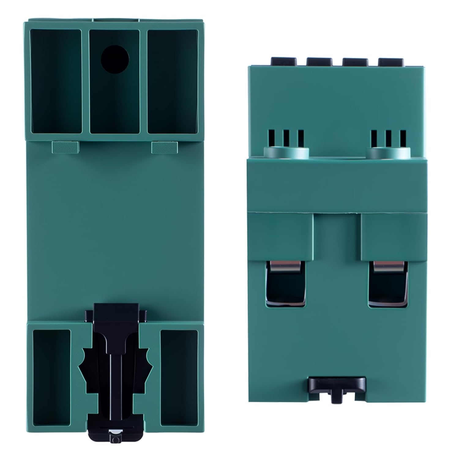
Figure 7.2: Side View
This image shows a side view of the voltage protector, highlighting its compact design and DIN rail mounting clips.
8. Maintenance
The JOYELEC Voltage Protector is designed for minimal maintenance. However, regular checks can ensure its longevity and reliable operation:
- Visual Inspection: Periodically inspect the device for any signs of physical damage, loose connections, or discoloration.
- Cleaning: If necessary, gently clean the exterior of the device with a dry, soft cloth. Do not use abrasive cleaners or solvents.
- Connection Check: Ensure all wiring connections remain tight and secure.
- Functionality Test: If possible and safe to do so, periodically test the protection functions by simulating an overvoltage, undervoltage, or overcurrent condition (e.g., using a test power supply) to confirm the device trips as expected.
CAUTION: Always disconnect power before performing any maintenance or inspection to avoid electrical hazards.
9. Troubleshooting
If you encounter issues with your JOYELEC Voltage Protector, refer to the following common troubleshooting steps:
| Problem | Possible Cause | Solution |
|---|---|---|
| Device does not power on. | No input power; incorrect wiring; internal fault. | Check power supply and circuit breaker. Verify wiring connections. If problem persists, contact support. |
| Device trips frequently. | Voltage/current fluctuations are common; protection settings are too sensitive. | Monitor power quality. Adjust overvoltage/undervoltage/overcurrent settings to appropriate levels for your application. |
| Display shows incorrect voltage/current. | Measurement inaccuracy; sensor issue. | Compare reading with a calibrated multimeter. If significantly different, contact support. |
| Device does not reset automatically. | Reset time setting is too long; fault condition still present. | Check reset time setting. Ensure the voltage/current has returned to normal operating range. |
For issues not covered here, please contact JOYELEC customer support.
10. Warranty and Support
JOYELEC products are manufactured to high-quality standards. This product comes with a standard manufacturer's warranty against defects in materials and workmanship. Please refer to your purchase documentation for specific warranty terms and duration.
For technical support, warranty claims, or service inquiries, please contact your retailer or JOYELEC customer service through the contact information provided with your purchase or on the official JOYELEC website.