1. Introduction
This manual provides comprehensive instructions for the UeeKKoo ESP32-P4-Module-DEV-KIT, a high-performance development board designed for advanced IoT and Human-Machine Interface (HMI) applications. It integrates the powerful ESP32-P4 and ESP32-C6 chips, offering robust processing capabilities, Wi-Fi 6, and Bluetooth 5/BLE connectivity.
The board features rich human-machine interfaces, including MIPI-CSI, MIPI-DSI, SPI, I2S, I2C, LED PWM, MCPWM, RMT, ADC, UART, and TWAI. It also supports USB OTG 2.0 HS, an onboard RJ45 Ethernet port with reserved PoE functionality, and a 40-pin GPIO header compatible with some Raspberry Pi HATs.

Image: The UeeKKoo ESP32-P4-Module-DEV-KIT development board.
2. Package Contents
Verify that all items listed below are included in your package:
- ESP32-P4-Module-DEV-KIT x1
- 8Ω 2W speaker x1

Image: The ESP32-P4-Module-DEV-KIT board and the included 8Ω 2W speaker.
3. Key Features
The ESP32-P4-Module-DEV-KIT offers a robust set of features for diverse applications:
- High-Performance MCU: Features a RISC-V 32-bit dual-core and single-core processor architecture.
- Memory: Includes 128 KB HP ROM, 16 KB LP ROM, 768 KB HP L2MEM, 32 KB LP SRAM, and supports up to 32MB PSRAM with onboard 16MB Nor Flash.
- Multimedia Capabilities: Provides image and voice processing interfaces including JPEG Codec, Pixel Processing Accelerator, Image Signal Processor, and H.264 encoder.
- Connectivity: Supports Wi-Fi 6 and Bluetooth 5/BLE. Common peripherals include MIPI-CSI, MIPI-DSI, USB 2.0 OTG, Ethernet, SDIO 3.0 TF card slot, microphone, speaker header, and RTC battery header.
- GPIO: Adopts 2*20 GPIO headers with 28 remaining programmable GPIOs.
- Security Features: Secure Boot, Flash Encryption, cryptographic accelerators, and TRNG. Hardware access protection mechanisms enable Access Permission Management and Privilege Separation.
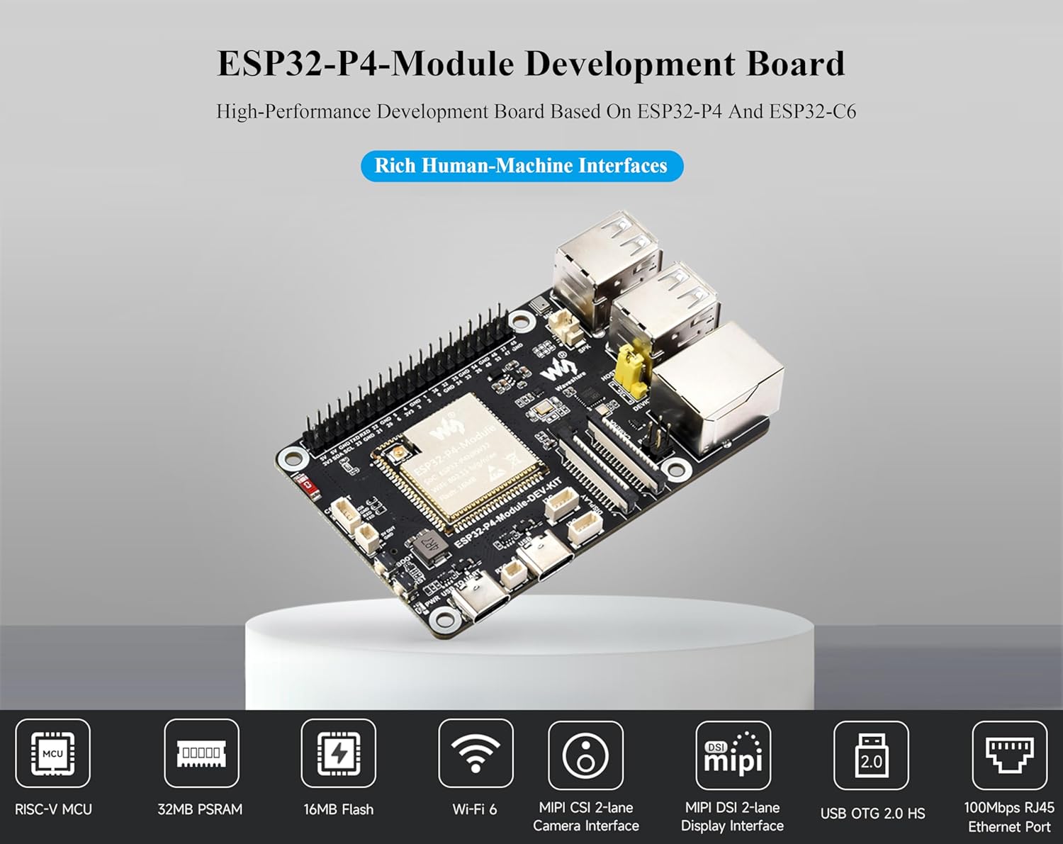
Image: Overview of the ESP32-P4-Module Development Board's main features.
4. Hardware Overview and Pin Definition
This section details the physical components and pin assignments of the ESP32-P4-Module-DEV-KIT.

Image: Labeled components, pin definitions, and dimensions of the ESP32-P4-Module-DEV-KIT.
4.1. Onboard Components
- ESP32-P4-Module: Built-in ESP32-P4NRW32, ESP32-C6, 16MB Nor Flash.
- Display interface: MIPI 2-lane.
- Camera interface: MIPI 2-lane.
- Type-C UART connector: For power supply, program burning, and debugging.
- RTC battery header: For connecting a rechargeable RTC battery (supports rechargeable RTC batteries only).
- Type-C connector: For power supply and program burning.
- I2C header.
- PoE module header: Connects to external PoE module for PoE power supply function.
- Onboard microphone.
- Speaker header: MX1.25 2P connector, supports 8Ω 2W speaker.
- Type-A ports.
- USB OTG 2.0 high-speed ports: Switching to HOST or DEVICE via jumper.
- RJ45 100M Ethernet port.
- 40PIN GPIO header.
- ESP32-C6 SMD Antenna: SDIO 3.0 interface protocol, extending Wi-Fi 6 / Bluetooth 5.
- ESP32-C6 UART header.
- 5V power header.
- BOOT button: Press it when powering on or resetting to enter download mode.
- RST Reset button.
- Power supply indicator.
- TF card slot.
- SDIO 3.0 interface protocol.
4.2. Pin Definition
The 40PIN GPIO header provides various connections. Refer to the diagram above for specific pin assignments including Power, GND, GPIO, I2C, and UART pins.
5. Setup Instructions
5.1. Initial Power-Up
- Connect the ESP32-P4-Module-DEV-KIT to a 5V power source using one of the Type-C USB ports.
- Observe the power indicator LED to confirm the board is receiving power.
5.2. Connecting Peripherals
- Speaker: Connect the included 8Ω 2W speaker to the designated speaker header (MX1.25 2P connector).
- Display: If using a MIPI-DSI display, connect it to the MIPI 2-lane display interface.
- Camera: If using a MIPI-CSI camera, connect it to the MIPI 2-lane camera interface.
- Ethernet: Connect an Ethernet cable to the RJ45 100M Ethernet port for network connectivity.
- USB Devices: Use the USB OTG 2.0 high-speed ports for connecting USB peripherals. Ensure the jumper is set correctly for HOST or DEVICE mode.
- SD Card: Insert a TF card into the TF card slot for additional storage.

Image: Examples of connecting peripherals to the development board.
6. Operating Instructions
6.1. Development Environment
To begin development, you will need to set up a suitable environment. The ESP32-P4-Module-DEV-KIT is compatible with various development tools and SDKs provided by Espressif.
- Refer to the official Espressif documentation for setting up the ESP-IDF (Espressif IoT Development Framework).
- Connect the board to your computer via the Type-C UART connector for programming and serial monitoring.
6.2. Programming the Board
- Ensure your development environment is correctly configured.
- Press and hold the BOOT button while powering on or resetting the board to enter download mode.
- Use your chosen development tool to flash your firmware onto the board.
- After flashing, press the RST (Reset) button to run your program.
6.3. Using Wi-Fi and Bluetooth
The integrated ESP32-C6 module provides Wi-Fi 6 and Bluetooth 5/BLE connectivity. Utilize the appropriate SDK functions within your code to configure and use these wireless features.

Image: Wi-Fi 6 and Bluetooth 5 support, and PoE power supply option.
7. Development Resources
For detailed technical documentation, examples, and tutorials, please refer to the online development resources provided by UeeKKoo and Espressif:
- UeeKKoo Online Resources: bit.ly/4jUag8V
- Espressif Official Documentation: Visit the Espressif website for the latest ESP-IDF documentation and chip datasheets.
8. Technical Specifications
| Feature | Specification |
|---|---|
| Brand | UeeKKoo |
| Model Name | ESP32-P4-Module-DEV-KIT |
| Processor | ESP32-P4 (400MHz dual-core RISC-V), ESP32-C6 |
| RAM | Up to 32MB PSRAM, 32KB LP SRAM, 768KB HP L2MEM |
| Flash Memory | 16MB Nor Flash |
| Wireless Connectivity | Wi-Fi 6, Bluetooth 5/BLE |
| Wired Connectivity | RJ45 100M Ethernet, USB OTG 2.0 HS |
| Interfaces | MIPI-CSI, MIPI-DSI, SPI, I2S, I2C, LED PWM, MCPWM, RMT, ADC, UART, TWAI, SDIO 3.0 |
| Operating System Support | Linux (via SDKs) |
| Dimensions | Approximately 85.00 x 56.00 mm (Refer to diagram for precise outline) |
| Weight | 0.32 ounces |
| Included Components | ESP32-P4-Module-DEV-KIT x1, 8Ω 2W speaker x1 |
9. Maintenance
- Cleaning: Use a soft, dry cloth to clean the board. Avoid using liquids or solvents.
- Storage: Store the development board in a dry, anti-static environment when not in use.
- Firmware Updates: Regularly check the official Espressif and UeeKKoo resources for firmware and SDK updates to ensure optimal performance and security.
- Handling: Always handle the board by its edges to avoid touching sensitive components and to prevent electrostatic discharge.
10. Troubleshooting
10.1. Power Issues
- Board not powering on: Ensure the USB-C cable is securely connected to a 5V power source. Try a different USB-C cable or power adapter. Check the power indicator LED.
10.2. Programming Issues
- Firmware not flashing:
- Verify the board is in download mode (press and hold BOOT button during power-up/reset).
- Ensure correct drivers are installed for the USB-UART bridge.
- Check your development environment settings and serial port selection.
10.3. Connectivity Issues (Wi-Fi/Bluetooth/Ethernet)
- No Wi-Fi/Bluetooth connection:
- Verify your code correctly initializes and configures the wireless modules.
- Ensure the ESP32-C6 SMD antenna is not obstructed.
- Ethernet not working:
- Check the Ethernet cable connection.
- Verify your code correctly initializes the Ethernet interface.
For further assistance, consult the online development resources or contact UeeKKoo support.
11. Warranty and Support
For information regarding product warranty, returns, or technical support, please refer to the UeeKKoo official website or contact their customer service directly through the platform where the product was purchased.
Online resources and tutorials are available at: bit.ly/4jUag8V


