1. Introduction
Thank you for choosing the EVTSCAN MPPT Solar Charge Controller. This device is designed to efficiently manage power flow from your solar panels to your battery bank, ensuring optimal charging and system protection. Utilizing advanced Maximum Power Point Tracking (MPPT) technology, it maximizes solar energy utilization, achieving up to 99% conversion efficiency. This manual provides essential information for the safe and effective operation of your solar charge controller.

Figure 1: Front view of the EVTSCAN MPPT Solar Charge Controller (MPK2-60A).
2. Safety Information
Please read all safety instructions carefully before installation and operation. Failure to follow these instructions may result in electric shock, fire, or serious injury.
- Ensure all wiring is correctly polarized and securely connected to prevent damage to the controller and connected devices.
- Do not attempt to disassemble or repair the controller yourself. Refer to qualified personnel for service.
- Install the controller in a well-ventilated area, away from flammable materials and direct sunlight.
- Verify that the solar panel array's open-circuit voltage (Voc) does not exceed the controller's maximum PV voltage (DC150V).
- Always disconnect the solar panel and battery power before performing any maintenance or wiring.
The controller features multiple built-in protections for enhanced safety:
- High/Low Voltage Protection
- Overload Protection
- Overheating Protection
- Positive and Negative Polarity Reverse Protection
- Output Short Circuit Protection
- Overcurrent Protection
- Damage Protection
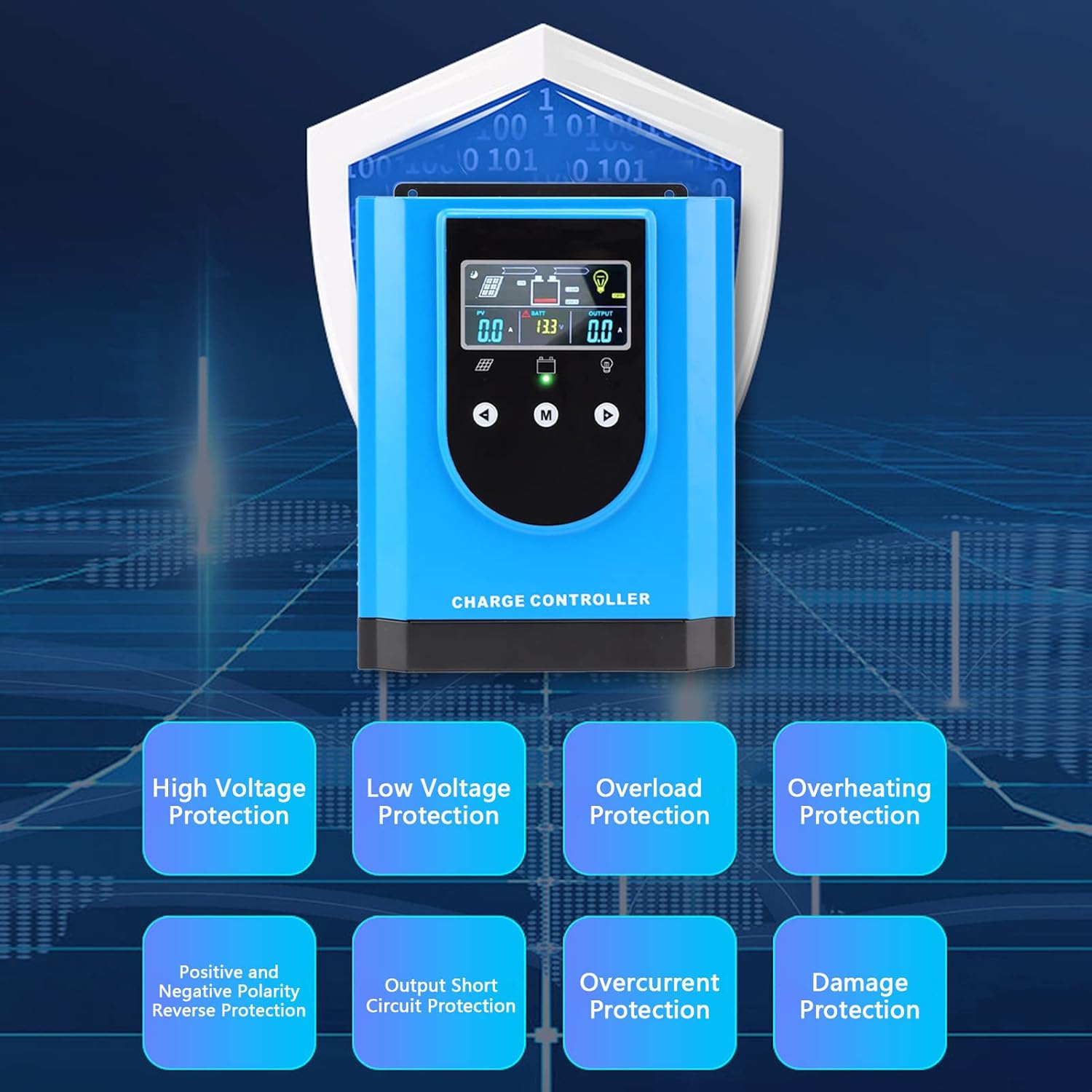
Figure 2: Overview of the controller's comprehensive safety features.
3. Product Overview and Components
The EVTSCAN MPPT Solar Charge Controller is housed in a durable aluminum alloy and ABS casing, designed for robust performance and heat dissipation. Key components include the digital display, control buttons, and various connection terminals.

Figure 3: Top view highlighting the digital display and control interface.

Figure 4: Bottom view displaying the connection terminals and ports.

Figure 5: Front view with the integrated cooling fan.
4. Specifications
| Feature | Specification |
|---|---|
| Item Type | Solar Charge Controller |
| Material | Aluminum Alloy, ABS |
| Rated Voltage | DC12V / 24V / 36V / 48V (Auto-sensing) |
| Maximum Photovoltaic Voltage | DC150V |
| Color | Blue |
| Item Model Number | EVTSCANpg49f6daok-13 |
| Package Dimensions | 12.2 x 9.84 x 5.91 inches |
| Item Weight | 8.69 pounds |
5. Setup and Installation
5.1 Package Contents
Before installation, please verify that all items are present in the package:
- 1 x EVTSCAN MPPT Solar Charge Controller (MPK2-60A)
- 1 x User Manual
- 1 x Connection Cable (for temperature sensor or communication)
5.2 Installation Steps
Follow these steps for proper installation. Ensure all power sources are disconnected before making any connections.
- Mounting the Controller: Choose a dry, well-ventilated location, preferably indoors, away from direct sunlight and moisture. Mount the controller vertically on a wall or suitable surface using appropriate fasteners. Ensure adequate clearance around the unit for proper heat dissipation.
- Connecting the Battery: Connect the battery to the controller's battery terminals (marked 'BATTERY' or with battery symbols). Ensure correct polarity: positive to positive, negative to negative. This connection must be made first to allow the controller to detect the system voltage.
- Connecting the Solar Panels: Connect the solar panel array to the controller's PV input terminals (marked 'SOLAR PANEL' or with PV symbols). Ensure correct polarity. Verify that the open-circuit voltage (Voc) of your solar array does not exceed the controller's maximum PV input voltage (DC150V).
- Connecting the DC Load (Optional): If you are connecting a DC load directly to the controller, connect it to the DC load output terminals (marked 'DC LOAD' or with load symbols). Ensure correct polarity. Note that the load output is typically for smaller DC loads and may have current limitations.
- Connecting the Temperature Sensor (Optional): If included, connect the external temperature sensor to the designated port (marked 'TEMP SENSOR'). This allows the controller to adjust charging parameters based on battery temperature for optimal performance and lifespan.
- Power On: Once all connections are secure and verified, the controller will power on automatically. The digital display will illuminate, showing current system parameters.
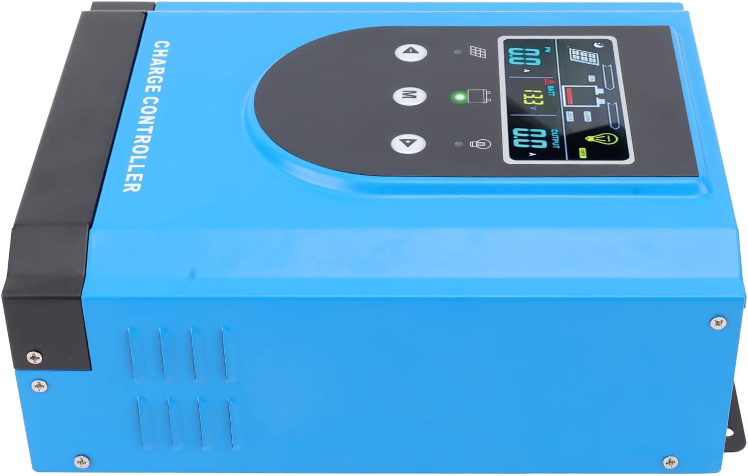
Figure 6: Side view, illustrating mounting points and ventilation.
6. Operating Instructions
6.1 Digital Display Interface
The controller features an interactive digital display for easy parameter setting and real-time monitoring. The display shows various system parameters such as PV voltage, battery voltage, output current, and charging status.
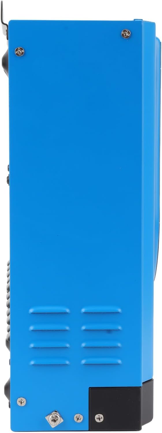
Figure 7: Close-up of the digital display.
Use the control buttons (Up, Down, M for Menu) to navigate through the display screens and adjust settings. Refer to the on-screen prompts for specific parameter adjustments.
6.2 Battery Compatibility and Activation
The controller is compatible with both lead-acid and lithium batteries. For lithium batteries, it includes a self-activation function, simplifying the setup process.
6.3 RS485 Communication (Optional)
The controller may include an RS485 communication port, allowing for remote monitoring and control via compatible software or devices. This feature enables advanced system management and data logging.
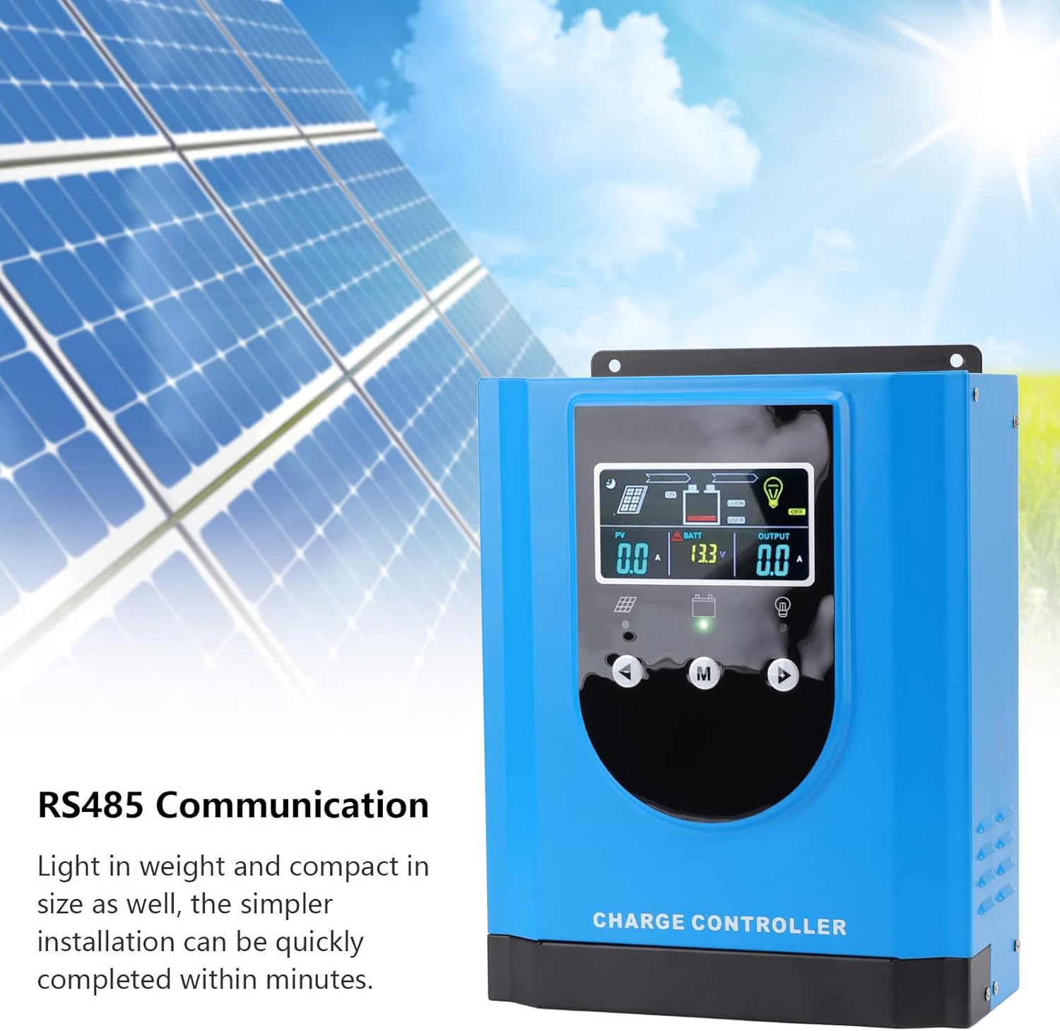
Figure 8: RS485 Communication feature.
7. Maintenance
Regular maintenance ensures the longevity and optimal performance of your solar charge controller.
- Cleaning: Periodically clean the controller's exterior with a dry, soft cloth. Ensure ventilation openings are free from dust and debris. Do not use liquid cleaners.
- Connection Check: Annually inspect all wiring connections for tightness and corrosion. Loose connections can cause overheating and poor performance.
- Environmental Check: Ensure the installation environment remains dry and within the specified operating temperature range.
- System Monitoring: Regularly check the digital display for any error codes or unusual readings.
8. Troubleshooting
This section addresses common issues you might encounter with your solar charge controller.
| Problem | Possible Cause | Solution |
|---|---|---|
| Controller not powering on | Battery not connected or low voltage; reversed battery polarity. | Ensure battery is connected first and has sufficient voltage. Check battery polarity. |
| No PV input/charging | Solar panels not connected; reversed PV polarity; insufficient sunlight; PV voltage too low/high. | Check PV connections and polarity. Ensure adequate sunlight. Verify PV voltage is within controller's operating range. |
| Load not working | Load output disabled; overload; short circuit; reversed load polarity. | Check load settings on display. Reduce load. Check for short circuits. Verify load polarity. |
| Overheating warning | Poor ventilation; excessive ambient temperature; prolonged high current operation. | Improve ventilation around controller. Reduce load if possible. Ensure ambient temperature is within limits. |
9. Wide Application
The EVTSCAN MPPT Solar Charge Controller is versatile and suitable for a wide range of applications, including:
- Residential and Commercial Solar Power Systems
- Solar Street Lights
- Solar Chargers
- Light Boxes
- Recreational Vehicles (RVs)
- Off-grid Cabins and Remote Power Systems

Figure 9: Examples of the controller's diverse applications.
10. Warranty and Support
For warranty information, technical support, or service inquiries, please contact EVTSCAN customer service through the retailer where the product was purchased or visit the official EVTSCAN website. Please have your model number (MPK2-60A) and purchase details ready when contacting support.


