1. Introduction
This manual provides detailed instructions for the safe and effective use of the coczow PM8200A Voltage and Continuity Tester. Please read this manual thoroughly before operating the device to ensure proper functionality and to prevent potential hazards.
2. Safety Information
WARNING: Electrical shock hazard. Always exercise extreme caution when working with electrical circuits. Failure to follow safety instructions may result in serious injury or death.
- Do not use the tester if it appears damaged or if the test leads are compromised.
- Verify the tester's functionality on a known live circuit before use.
- Always wear appropriate personal protective equipment (PPE), such as insulated gloves and safety glasses.
- Do not exceed the maximum rated voltage of 1200V AC / 1500V DC.
- The device is rated IP65 for protection against dust and water jets. While it can be used in damp conditions, avoid submerging it.
- Ensure the battery compartment is securely closed before use.
- Refer to local electrical codes and safety regulations.
3. Package Contents
Upon opening the package, please verify that all items listed below are present and undamaged:
- coczow PM8200A Voltage and Continuity Tester
- 1.5V AAA Batteries (x2)
- User Manual (this document)
- Protective Rubber Cover for Test Leads

Image: The coczow PM8200A Voltage and Continuity Tester, showing its main body and connected test leads.
4. Product Features
The coczow PM8200A is a versatile electrical tester designed for various applications. Key features include:
- Automatic Range Adjustment: Simplifies operation by automatically selecting the appropriate measurement range.
- Wide Voltage Measurement: Measures AC voltage up to 1200V and DC voltage up to 1500V.
- Phase Sequence Test: Indicates the phase rotation for three-phase AC systems (150V – 400V, 50Hz – 60Hz).
- Continuity Test: Detects continuity with an audible buzzer and LED indication (resistance ≤ 100 kΩ).
- RCD Test: Performs Residual Current Device (RCD) testing at 230V (40-500Hz) with a trip current of 30mA ~ 40mA.
- Single Pole Phase Detection: Identifies live or neutral wires using a single test pen.
- High Voltage Indicator: Visual warning for high voltage presence.
- Low Battery Warning: Alerts when battery replacement is needed.
- IP65 Protection: Dust-tight and protected against water jets, suitable for various environments.
- Built-in Lighting Function: Provides illumination for working in dimly lit areas.
- Data Hold Function: Freezes the displayed measurement for easier reading.

Image: Visual representation of the PM8200A's key functions, including AC/DC voltage measurement, phase sequence test, RCD test, IP65 rating, no battery detection, connectivity measurement, lighting function, and data hold.
5. Specifications
| Parameter | Value |
|---|---|
| Model Number | PM8200A |
| AC Voltage Range | 12V ~ 1200V AC |
| DC Voltage Range | 12V ~ 1500V DC |
| Phase Sequence Test Voltage | 150V ~ 400V AC (50Hz – 60Hz) |
| Continuity Resistance | ≤ 100 kΩ |
| RCD Test Voltage | 230V (40-500Hz) |
| RCD Test Trip Current | 30mA ~ 40mA |
| Protection Rating | IP65 |
| Safety Category | CATIV 600V, CATII 1000V |
| Power Source | 2 x 1.5V AAA Batteries |
| Dimensions (L x W x H) | 27.5 x 8 x 3.4 cm |
| Weight | 440 g |
6. Setup
6.1 Battery Installation
- Locate the battery compartment cover on the back of the tester.
- Use a suitable screwdriver to loosen the screws securing the battery cover.
- Insert two (2) 1.5V AAA batteries, ensuring correct polarity (+/-) as indicated inside the compartment.
- Replace the battery cover and tighten the screws securely to maintain the IP65 rating.
Note: The tester can perform basic voltage detection without batteries, but full functionality, including RCD test, lighting, and data hold, requires batteries.
7. Operating Instructions
The PM8200A features automatic range selection, simplifying most measurements. The LED indicators provide clear visual feedback.
7.1 AC/DC Voltage Measurement
- Connect the test leads to the circuit or component to be measured.
- The tester will automatically detect AC or DC voltage and display the approximate voltage level via the LED indicators (12V, 24V, 50V, 120V, 230V, 400V, 690V, 1000V, 1500V).
- For DC voltage, the '+' or '-' LED will indicate polarity.

Image: The PM8200A tester being used to measure voltage within an electrical distribution panel, demonstrating its application for AC/DC voltage measurement.
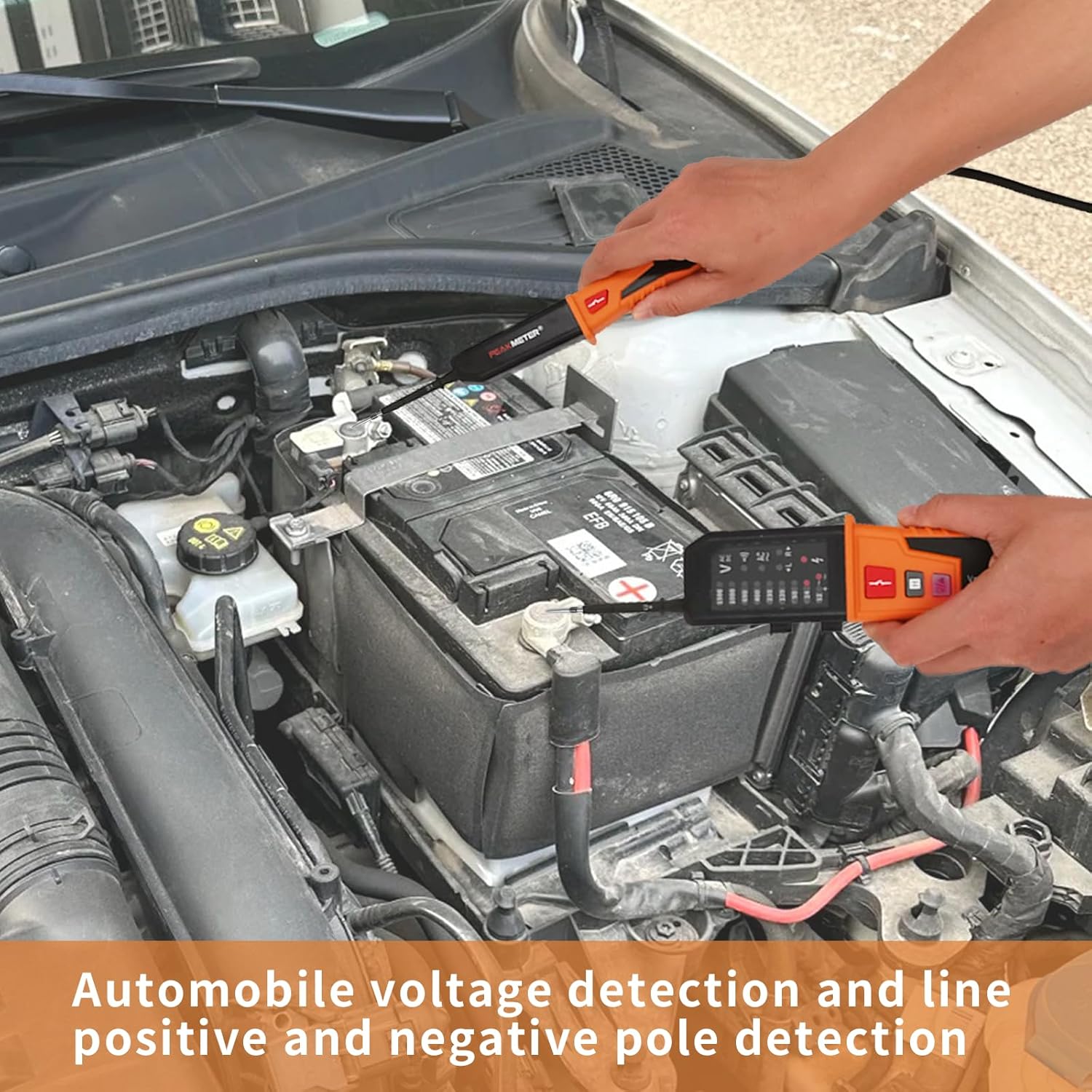
Image: The PM8200A tester being used to detect voltage and polarity on a car battery, illustrating its use for automotive electrical systems.
7.2 Continuity Test
- Ensure the circuit is de-energized before performing a continuity test.
- Connect the test leads across the component or circuit path you wish to test.
- If continuity exists (resistance ≤ 100 kΩ), the continuity LED will illuminate, and an audible buzzer will sound.
7.3 Phase Sequence Test (Three-Phase Systems)
- Connect the test leads to the three phases of the AC system.
- The 'L' or 'R' LED indicators will illuminate to show the phase rotation (Left or Right).
- This test is applicable for three-phase AC systems within the voltage range of 150V to 400V (50Hz-60Hz).

Image: The PM8200A tester conducting a phase sequence test on a multi-phase electrical connector, indicating the direction of phase rotation.
7.4 RCD Test
- Connect the test leads to the circuit protected by an RCD.
- Press the RCD test button (usually marked with an RCD symbol).
- The RCD should trip within 10 seconds if it is functioning correctly.
- The tester is designed for RCDs with a trip current of 30mA to 40mA at 230V (40-500Hz).

Image: The PM8200A tester performing an RCD (Residual Current Device) test on a power strip, demonstrating the safety function check.
7.5 Single Pole Phase Detection (Live/Neutral Wire)
- Hold the main body of the tester and touch the 'L2' test pen to the wire you want to test.
- The tester will indicate if the wire is a live wire or a neutral wire.

Image: The PM8200A tester using a single test pen to detect a live wire on a power strip, illustrating the single pole phase detection feature.
7.6 Lighting Function
Press the dedicated lighting button (often marked with a light bulb symbol) to activate the built-in flashlight for illumination in dark work areas.
7.7 Data Hold Function
Press the 'H' button to freeze the current measurement on the display. Press it again to release the hold and resume live measurement.
8. Maintenance
- Cleaning: Wipe the tester with a dry, soft cloth. Do not use abrasive cleaners or solvents.
- Battery Replacement: Replace batteries when the low battery indicator appears to ensure accurate readings and full functionality. Always use 1.5V AAA batteries.
- Storage: Store the tester in a cool, dry place away from direct sunlight and extreme temperatures. If storing for extended periods, remove the batteries to prevent leakage.
- Inspection: Regularly inspect the test leads and the tester body for any signs of damage, cracks, or frayed insulation. Do not use if damaged.
9. Troubleshooting
| Problem | Possible Cause | Solution |
|---|---|---|
| No LED indication / Tester not turning on | Dead or incorrectly installed batteries. | Check battery polarity and replace with new 1.5V AAA batteries. |
| Inaccurate voltage readings | Low battery; Damaged test leads; Exceeding measurement range. | Replace batteries; Inspect and replace test leads if damaged; Ensure voltage is within specified range. |
| Continuity test not working | Circuit is open; Resistance is too high (>100 kΩ); No batteries installed. | Verify circuit path; Ensure resistance is within range; Install fresh batteries. |
| RCD test not tripping | RCD is faulty; Incorrect voltage/frequency; Tester malfunction. | Consult a qualified electrician to check the RCD; Verify circuit parameters; Contact support if tester is suspected faulty. |
10. Warranty and Support
The coczow PM8200A Voltage and Continuity Tester is designed for reliability and durability. For warranty information, technical support, or service inquiries, please refer to the contact details provided with your purchase or visit the official coczow website.
Please retain your proof of purchase for warranty claims.