1. Introduction
This manual provides detailed instructions for the installation, operation, and maintenance of the VCELINK RJ45 Tool-Free CAT6 Field Termination Plugs. These connectors are designed for efficient and reliable termination of CAT6 and CAT5E Ethernet cables without the need for specialized crimping tools. Please read this manual thoroughly before proceeding with installation to ensure proper functionality and safety.
2. Product Overview
The VCELINK RJ45 Tool-Free CAT6 Field Termination Plugs offer a convenient solution for creating custom-length Ethernet cables or repairing existing ones. Key features include:
- Tool-Free Design: Eliminates the need for a crimping tool, simplifying installation.
- High-Speed Transmission: Supports data transfer rates up to 1Gbps.
- Gold-Plated Contacts: Ensures reliable signal transmission and corrosion resistance.
- Nut-Type Strain Relief Boot: Provides secure cable retention and protection against stretching.
- Reusable: Connectors can be disassembled and reassembled if errors occur during termination.
- Compact Size: Designed to fit side-by-side in network devices like switches and routers.

Image: A set of six VCELINK RJ45 Tool-Free CAT6 Field Termination Plugs, showcasing their compact design.

Image: Detailed view of the connector components, highlighting the nut-type strain relief boot, internal PCB for signal transmission, and gold-plated contacts.
3. Setup and Installation
The VCELINK RJ45 Tool-Free connectors are designed for easy installation. While no crimping tool is required, common cutting tools such as wire strippers and cutters are necessary.
Required Tools:
- Wire Stripper
- Wire Cutter
Installation Steps:

Image: A nine-step visual guide demonstrating the complete installation process for the VCELINK RJ45 Tool-Free connector.
- Insert the Strain Relief Boot: Slide the nut-type strain relief boot onto the Ethernet cable.
- Strip the Cable Jacket: Carefully strip approximately 2 cm (0.8 inches) of the outer jacket from the Ethernet cable, exposing the twisted pairs.
- Arrange and Straighten Wires: Untwist the wire pairs and straighten each individual wire. Refer to the T568A or T568B wiring standard for correct color order.
- Thread Wires into Load Bar: Insert each straightened wire into the corresponding color-coded slot on the load bar. Ensure the wires are fully seated according to your chosen wiring standard (T568A or T568B).
- Cut Excess Wires: Use a wire cutter to trim any excess wire protruding from the load bar, ensuring a clean, flush cut.
- Align and Press: Align the load bar with the main connector body, ensuring the grooves match. Press the two parts firmly together until they click into place.
- Close the Cover: Secure the clear cover over the terminated wires.
- Tighten the Nut: Slide the strain relief boot forward and tighten it onto the connector body to secure the cable.
- Complete: The connector is now terminated and ready for use.

Image: Diagram illustrating the T568A and T568B wiring color codes for Ethernet cables, essential for correct termination.
4. Operating Instructions
Once properly terminated, the VCELINK RJ45 Tool-Free connector functions as a standard Ethernet plug. Simply insert the connector into a compatible RJ45 port on a network device (e.g., computer, router, switch, modem) until it clicks securely into place. To remove, press down on the release tab and gently pull the connector out of the port.

Image: Multiple VCELINK RJ45 connectors plugged side-by-side into a network switch, demonstrating their compact design for high-density applications.
5. Maintenance
These connectors require minimal maintenance. To ensure optimal performance:
- Keep the gold-plated contacts clean and free from dust or debris.
- Avoid excessive bending or pulling on the cable near the connector to prevent damage to the strain relief.
- Store unused connectors in a dry, clean environment.

Image: Visual representation of the connector's reusability, showing how it can be opened and re-terminated if needed.
6. Troubleshooting
If you experience issues with your network connection after installing the connector, consider the following:
- No Connection/Intermittent Connection:
- Verify that all wires are correctly seated in the load bar according to the T568A or T568B standard.
- Ensure the wires are fully trimmed and making proper contact with the gold pins.
- Check that the connector is fully inserted into the RJ45 port and the latch is engaged.
- Inspect the cable for any damage or breaks.
- Slow Network Speed:
- Confirm that the cable used is CAT6 or CAT5E and supports the desired speed.
- Re-check the wiring order for any cross-overs or misplacements that could degrade signal quality.
- Ensure the cable length does not exceed the maximum recommended length for CAT6 (100 meters for 1Gbps).
Due to the reusable design, you can carefully disassemble the connector to inspect and correct any wiring errors.
7. Specifications
| Model Number | KJ22BK-C6-6P-CA |
| Connector Type | RJ45 |
| Category | CAT6 / CAT5E |
| Wire Gauge Compatibility | 23-26 AWG (0.4-1.2mm Wire OD) |
| Cable Jacket OD Compatibility | 6.0-7.6mm |
| Transmission Speed | Up to 1 Gbps |
| Contact Material | Gold Plated |
| Dimensions (L x W x H) | 2.09 x 0.57 x 0.52 inches (53 x 14.5 x 13.2 mm) |
| Weight | 1.28 ounces (per 6 pack) |
| Compatible Devices | Modem, Personal Computer, Printer, Router, Server |
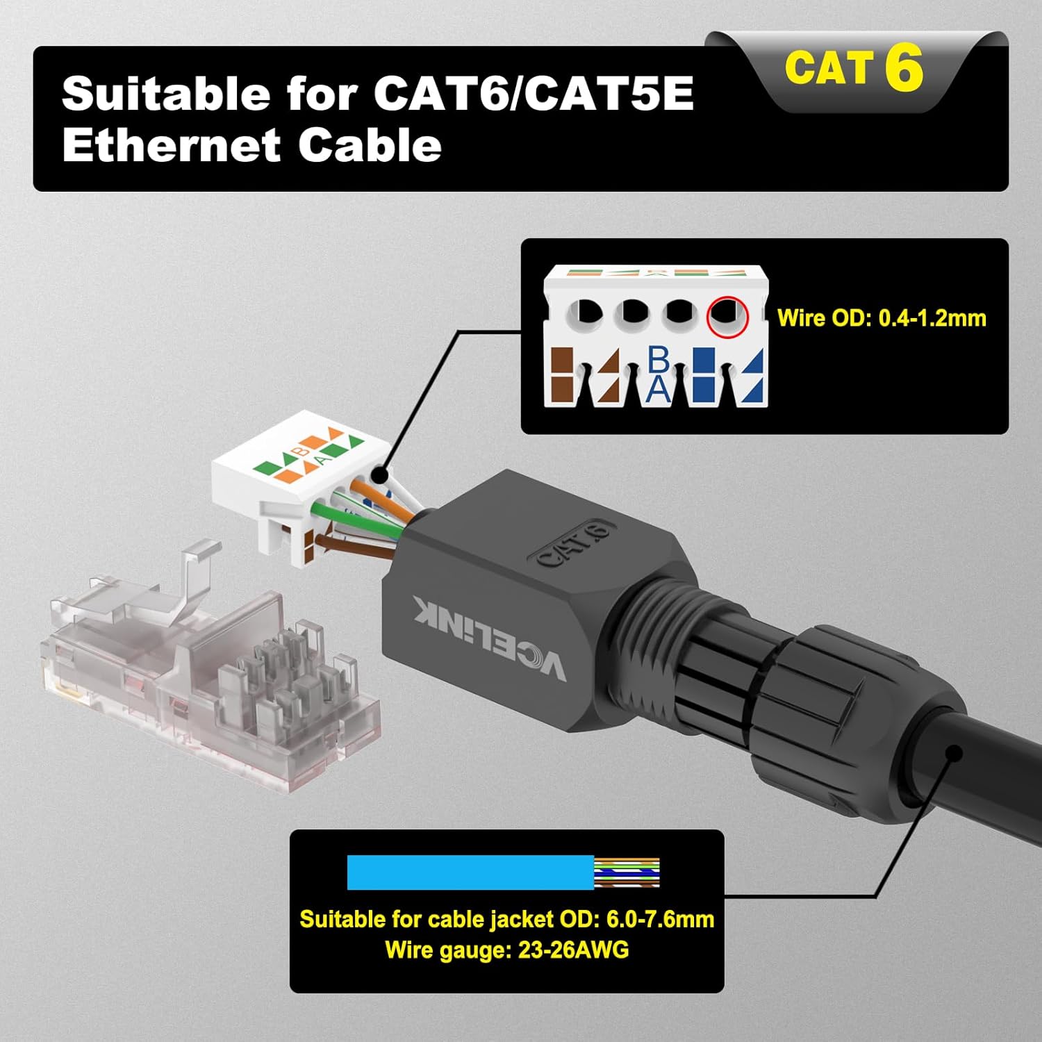
Image: Diagram detailing the compatibility with CAT6/CAT5E Ethernet cables, including wire OD, cable jacket OD, and wire gauge specifications.
8. Customer Support
VCELINK is committed to providing quality products and customer satisfaction. If you encounter any issues, have questions, or require assistance with your RJ45 Tool-Free connectors, please do not hesitate to contact VCELINK customer support. While specific warranty details are not provided in this manual, our team is available to help resolve any product-related concerns.


