1. Introduction
This manual provides detailed instructions for the installation, operation, and maintenance of your VBESTLIFE B75 Micro ATX Motherboard. Please read this manual thoroughly before proceeding with installation to ensure proper setup and functionality.
Key Features:
- Processor Support: Compatible with 2nd and 3rd generation Intel Core i3/i5/i7, E3/V2 series, Celeron G series, and Pentium G series processors for LGA 1155 socket.
- Memory: Two 240-pin DDR3 SDRAM slots supporting up to 16GB in dual-channel architecture at 1066/1333/1600 MHz.
- Storage: High-speed M.2 interface with jumper support for NVMe and NGFF connections, alongside two ATA2.0 (3Gb/s) ports and one ATA3.0 (6Gb/s) port.
- Video Output: Integrated VGA and HDMI outputs for 1080P HD video (requires CPU with integrated graphics).
- Construction: 8-layer PCB, 6-phase power supply, and all solid capacitors for enhanced stability and durability.
2. Package Contents
Verify that all items listed below are present in your package. If any item is missing or damaged, please contact your retailer.
- VBESTLIFE B75 Computer Motherboard
- I/O Shield
- SATA Data Cable
- Driver CD

Image: Contents of the motherboard package, showing the motherboard, driver CD, SATA cable, and I/O shield.
3. Motherboard Layout
Familiarize yourself with the various components and connectors on the VBESTLIFE B75 motherboard.

Image: Top-down view of the VBESTLIFE B75 motherboard, showing the LGA 1155 CPU socket, two DDR3 RAM slots, PCIe slots, SATA ports, and M.2 slot.

Image: Rear I/O panel of the VBESTLIFE B75 motherboard, displaying 4x USB 2.0, 2x USB 3.0, 1x VGA, 1x HDMI, 1x RJ45 LAN, and 3x audio ports.
4. Installation Guide
4.1. CPU Installation
Follow these steps carefully to install your LGA 1155 processor onto the motherboard.

Image: Step-by-step guide for CPU installation. It illustrates how to open the CPU socket, align the processor using the triangle markers, gently place it, remove the protective cover, and secure it by closing the lever. Important warnings advise against touching CPU contacts or pins.
- Open the Socket: Gently press down on the CPU socket lever and lift it to open the socket retention mechanism.
- Align CPU: Carefully align the triangle symbol on your CPU with the corresponding triangle on the CPU socket. Ensure the CPU is oriented correctly.
- Place CPU: Gently place the CPU into the socket without forcing it. It should sit flush.
- Remove Cover: Remove the plastic protective cover from the CPU socket.
- Secure CPU: Lower the socket lever and press it down until it locks into place, securing the CPU.
Important: Avoid touching the CPU contacts or the pins within the CPU socket to prevent damage.
4.2. Memory (RAM) Installation
The B75 motherboard supports DDR3 memory modules. It has two 240-pin DDR3 SDRAM slots.
- Open Clips: Push the retention clips at both ends of the DIMM slot outwards.
- Align Module: Align the notch on the DDR3 memory module with the key in the DIMM slot.
- Insert Module: Insert the memory module firmly into the slot until the retention clips snap into place. Ensure both clips are fully closed.
For optimal performance, install memory modules in pairs to utilize dual-channel mode.
4.3. Storage Device Installation
The motherboard supports M.2 NVMe/NGFF SSDs and SATA hard drives/SSDs.
M.2 SSD Installation:
- Locate M.2 Slot: Identify the M.2 slot on the motherboard.
- Insert M.2 SSD: Gently insert the M.2 SSD into the slot at a 30-degree angle.
- Secure SSD: Push the SSD down and secure it with the provided screw.
- Jumper Setting: If applicable, adjust the M.2 jumper setting to select between NVMe or NGFF (SATA3.0 6Gb/s) mode based on your SSD type. Refer to the motherboard diagram for jumper locations.
SATA Drive Installation:
- Connect SATA Cable: Connect one end of the SATA data cable to a SATA port on the motherboard (2x SATA2.0, 1x SATA3.0).
- Connect to Drive: Connect the other end of the SATA data cable to your hard drive or SSD.
- Connect Power: Connect a SATA power cable from your power supply unit (PSU) to the storage drive.
4.4. Expansion Card Installation
The motherboard features one PCI Express x16 slot and one PCI Express x1 slot.
- Open Case Slot: Remove the metal bracket cover from the desired expansion slot on your PC case.
- Insert Card: Align your expansion card (e.g., graphics card in PCIe x16) with the slot and press down firmly until it is fully seated.
- Secure Card: Secure the card to the PC case with a screw or retention clip.
5. Operating Instructions
5.1. Initial Power-On and BIOS Setup
- Connect Power: Ensure all power connectors (24-pin ATX and 4-pin ATX 12V) are securely connected from your PSU to the motherboard.
- Connect Peripherals: Connect your monitor, keyboard, and mouse to the appropriate ports on the rear I/O panel.
- Power On: Press the power button on your PC case.
- Access BIOS: During startup, repeatedly press the DEL or F2 key (check your screen for the exact key) to enter the BIOS/UEFI setup utility.
- Configure Settings: In the BIOS, you can configure boot order, system time, and other hardware settings. Save changes and exit to proceed with operating system installation.
5.2. Video Output
The motherboard supports integrated graphics output via VGA and HDMI ports. To use these, your installed CPU must have integrated graphics capabilities.
- Connect your monitor to either the VGA or HDMI port on the motherboard's rear I/O panel.
- If a dedicated graphics card is installed, the system will typically prioritize its output. You may need to adjust BIOS settings to use integrated graphics if a dedicated card is present.
6. Maintenance and Care
Proper maintenance ensures the longevity and stable operation of your motherboard.
- Dust Removal: Regularly clean dust from the motherboard and other internal components using compressed air. Ensure the system is powered off and unplugged before cleaning.
- CMOS Battery: The motherboard uses a CR2032 battery for CMOS settings. If you experience issues with BIOS settings resetting, the battery may need replacement.
- Environmental Conditions: Operate the motherboard in a well-ventilated area, away from excessive heat, humidity, and direct sunlight.
7. Troubleshooting
This section addresses common issues you might encounter.
- No Power: Ensure all power cables (24-pin ATX, 4-pin ATX 12V) are securely connected. Check the power supply unit (PSU) and power button connections to the motherboard.
- No Display: Verify that the monitor is connected to the correct video output (motherboard's integrated graphics or dedicated graphics card). Ensure the CPU has integrated graphics if using motherboard video outputs. Reseat the RAM modules.
- System Instability/Crashes: Check for proper CPU and RAM installation. Ensure adequate cooling for the CPU. Update drivers and BIOS if necessary.
- Peripheral Not Detected: Ensure USB devices are properly connected. Check SATA cable connections for storage drives. Verify M.2 jumper settings for M.2 SSDs.
- BIOS Settings Resetting: This often indicates a depleted CMOS battery (CR2032). Replace the battery.
8. Specifications
Detailed technical specifications for the VBESTLIFE B75 Motherboard.
| Feature | Specification |
|---|---|
| Model | B75 |
| Material | PCB |
| CPU Socket | LGA1155 |
| CPU Support | 2nd/3rd Gen Core i3/i5/i7, E3/V2 series, Celeron G series, Pentium G series |
| Memory Slots | 2 x 240-pin DDR3 SDRAM |
| Max Memory | 16GB (Dual Channel) |
| Memory Frequency | 1066/1333/1600 MHz |
| Storage Ports | 2 x ATA2.0 (3Gb/s), 1 x ATA3.0 (6Gb/s), 1 x M.2 (NVMe/NGFF) |
| Integrated LAN | Realtek 10/100 Mbps |
| Expansion Slots | 1 x PCI Express x16, 1 x PCI Express x1 |
| Integrated Sound | Realtek ALC 6-channel HD sound codec |
| USB Ports (Rear) | 4 x USB 2.0, 2 x USB 3.0 |
| Video Outputs | 1 x VGA, 1 x High Definition Multimedia Interface (HDMI) |
| Other I/O | 1 x RJ45, 1 x 3-in-1 sound port |
| Power Interfaces | 1 x 24-pin ATX, 1 x 4-pin ATX 12V |
| Form Factor | M-ATX (Approx. 17 x 19cm / 6.69 x 7.48in) |
| CMOS Battery | CR2032 (Built-in) |
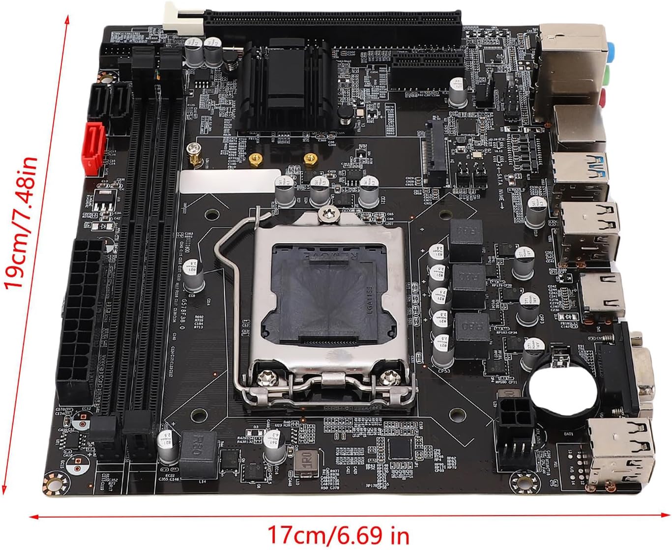
Image: Dimensions of the VBESTLIFE B75 motherboard, indicating its M-ATX form factor size.
9. Product Overview Video
Watch this video for a visual overview of a similar LGA1155 motherboard, demonstrating its components and features. While the video title refers to an H61 motherboard, the general layout and installation principles are applicable to the B75 model.
Video: An overview of an LGA1155 motherboard, showcasing its physical components, ports, and general design. This video provides a helpful visual aid for understanding motherboard structure and handling.
10. Warranty and Support
For warranty information and technical support, please refer to the documentation provided with your purchase or contact your retailer. Keep your proof of purchase for warranty claims.


