1. Introduction
This manual provides essential information for the safe and efficient installation, operation, and maintenance of your EARU Electric 3-Phase Auto Transfer Switch (ATS) - 440V 63A. Please read this manual thoroughly before installation and operation to ensure proper functionality and to prevent damage or injury.
The ATS is designed to provide uninterrupted power by automatically transferring loads between phases in a three-phase supply system. It features intelligent monitoring and protection against phase failure, over/under voltage, and overcurrent conditions, ensuring the stability and safety of connected equipment.
2. Safety Information
WARNING: Electrical shock hazard. Installation and servicing should only be performed by qualified personnel.
- Always disconnect power before installing or servicing the ATS.
- Ensure all wiring complies with local and national electrical codes.
- Verify correct voltage and current ratings before connecting the device.
- Do not operate the device if it appears damaged.
- Keep children away from electrical equipment.
3. Product Overview
The EARU Electric 3-Phase ATS is an intelligent device that continuously monitors your three-phase power supply. It automatically switches single-phase loads to a healthy phase in case of a phase failure or imbalance, ensuring continuous operation of critical equipment.
3.1. Package Contents
- 1 x EARU Electric 3-Phase Auto Transfer Switch (ATS)
3.2. Front Panel and Indicators

Image Description: The front panel of the ATS features a digital display showing voltage for L1, L2, L3 phases and current for L1. Below the display are indicators for Power, Over-voltage (>V), Under-voltage (<V), and Over-current (>I). Control buttons include 'SET' (Menu key), 'Digit+/Up', 'Digit-/Down', and 'Manual ON/OFF' (Power button).
The digital display provides real-time voltage readings for each phase (L1, L2, L3) and the current for L1. Status indicators alert you to the operational state and any detected faults:
- Power: Output indication.
- >V: Over-voltage indication.
- <V: Under-voltage indication.
- >I: Over-current indication.
Control buttons allow for parameter settings and manual operation:
- SET: Menu key for accessing settings.
- Digit+/Up: Increases value or navigates up in menus.
- Digit-/Down: Decreases value or navigates down in menus.
- Manual ON/OFF: Power button for manual control.
4. Setup and Installation
The ATS is designed for standard DIN rail mounting. Ensure sufficient space for ventilation and wiring connections.
4.1. Wiring Diagram
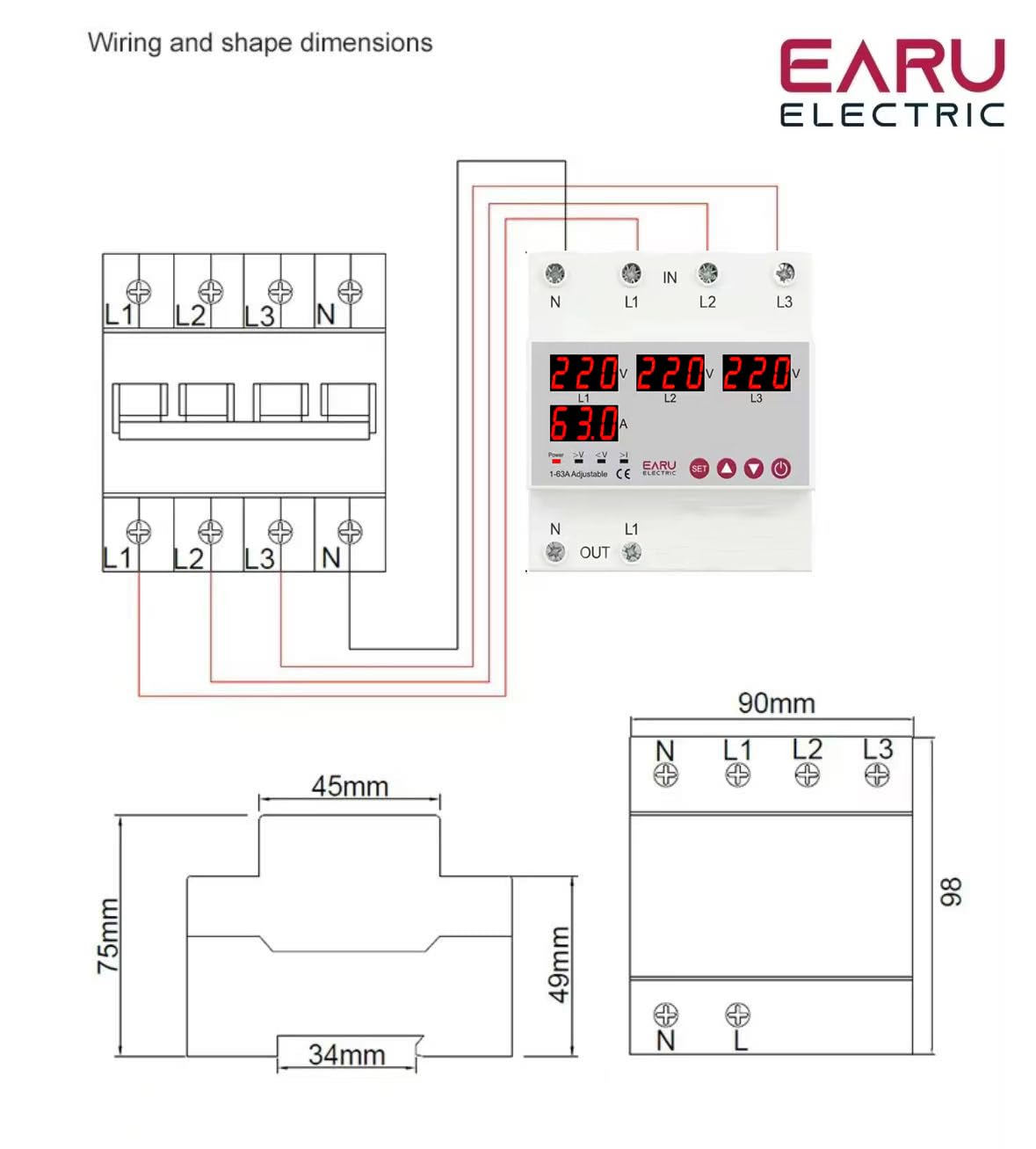
Image Description: A detailed wiring diagram illustrates the connection points for the ATS. The top terminals are labeled 'IN' with connections for N, L1, L2, L3. The bottom terminals are labeled 'OUT' with connections for N and L1. The diagram shows how to connect the three-phase input to the ATS and how a single-phase load (L1 and N) is connected to the output, with internal connections for phase monitoring and switching.
Follow the wiring diagram carefully. Incorrect wiring can lead to device malfunction or electrical hazards.
- Connect the incoming three-phase power supply (N, L1, L2, L3) to the 'IN' terminals.
- Connect the single-phase load (N, L1) to the 'OUT' terminals. The ATS will manage the phase transfer for the L1 output.
- Ensure all connections are secure and tightened to prevent loose contacts and overheating.
4.2. Initial Power-Up
After completing the wiring, restore power to the system. The ATS will power on and begin monitoring the phases. The digital display will show the current voltage readings for each phase. If all phases are stable and within acceptable limits, the ATS will provide power to the output.
5. Operating Instructions
The ATS operates automatically, but you can adjust its protection parameters to suit your specific requirements.
5.1. Understanding the Display and Indicators
The digital display continuously shows the real-time voltage of each phase (L1, L2, L3) and the current on L1. The indicator lights provide quick visual feedback on the device's status and any detected anomalies.
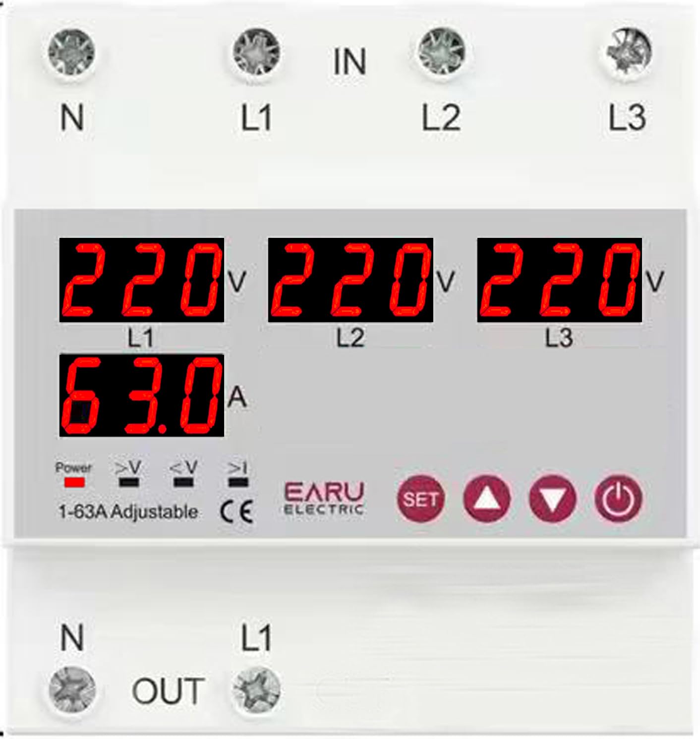
Image Description: A close-up view of the ATS digital display. It shows '220V' for L1, L2, and L3, and '63.0A' for L1 current. Below these readings are small indicator icons for Power, >V (Over-voltage), <V (Under-voltage), and >I (Over-current).
5.2. Adjusting Protection Parameters
Use the 'SET' button to enter the parameter setting mode. Use the 'Digit+/Up' and 'Digit-/Down' buttons to navigate through settings and adjust values. Press 'SET' again to confirm and save changes.
| Parameter | Setting Range | Default Setting |
|---|---|---|
| Over Current Protection Setting Range | 1-63A/100A | 30A |
| Continuous Over Current Protection Times | 0-20 Times | OFF |
| Over Voltage Protection Setting Range | 230-300V | 270V |
| Over Voltage Protection Recover Setting Range | 225-295V | 265V |
| Under Voltage Protection Setting Range | 140-210V | 170V |
| Under Voltage Protection Recover Setting Range | 145-215V | 175V |
| Voltage & Current Protection Recover Delay | 1-500s | 30s |
5.3. Automatic Phase Transfer
The ATS automatically monitors the three input phases (L1, L2, L3). If a phase failure or significant voltage imbalance (over/under voltage) is detected on the currently supplying phase, the device will automatically transfer the single-phase output load to a healthy, stable phase within the same supply. This process is designed to be seamless and rapid, minimizing power interruption to connected equipment.
5.4. Automatic Recovery
Once the primary phase recovers and stabilizes, the ATS will intelligently switch the load back to the primary source, ensuring optimal power distribution and preventing equipment damage from unstable power. The recovery delay can be configured as per your operational needs.
6. Maintenance
The EARU Electric ATS is designed for minimal maintenance. However, periodic checks are recommended to ensure optimal performance and longevity.
- Cleaning: Keep the device clean and free from dust and debris. Use a dry, soft cloth for cleaning. Do not use liquid cleaners.
- Connection Checks: Periodically inspect all wiring connections to ensure they remain tight and free from corrosion.
- Environmental Conditions: Ensure the operating environment remains within the specified temperature and humidity ranges.
7. Troubleshooting
If you encounter issues with your ATS, refer to the following common problems and solutions:
| Problem | Possible Cause | Solution |
|---|---|---|
| No power output | No input power; all phases unstable; device in fault state. | Check incoming power supply. Verify all phases are stable. Check fault indicators. |
| ">V" or "<V" indicator lit | Over-voltage or under-voltage detected on a phase. | Check input voltage stability. The ATS will automatically transfer if another phase is healthy. |
| ">I" indicator lit | Over-current detected on the output. | Reduce load on the output. Check for short circuits in the connected equipment. |
| Device not transferring phases | No healthy alternative phase available; transfer delay setting too long. | Ensure at least one healthy phase is present. Check and adjust the transfer delay settings. |
| Digital display not working | No power to the device; internal fault. | Check power supply. If power is present and display is off, contact support. |
For issues not covered here, please contact EARU customer support.
8. Specifications
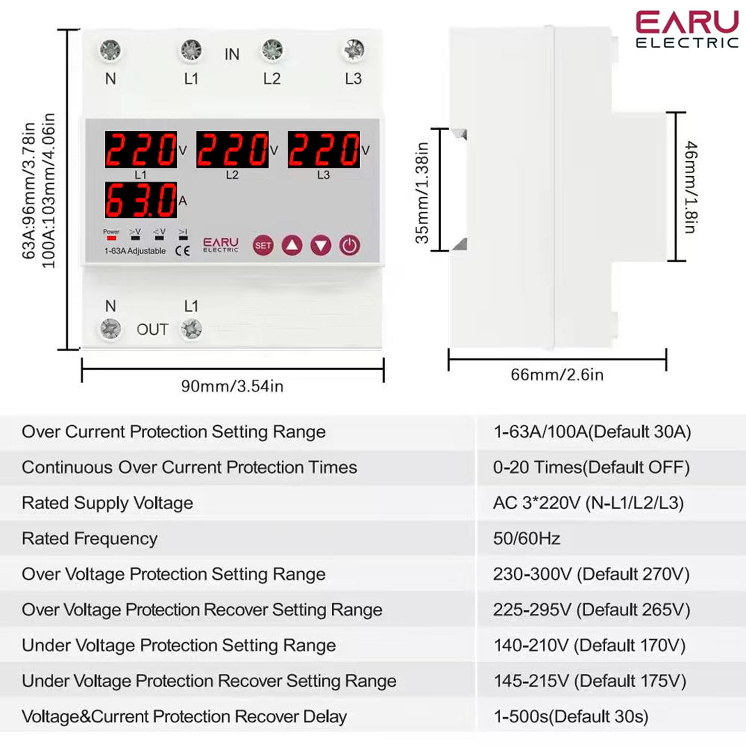
Image Description: This image displays the physical dimensions of the ATS (90mm width, 96mm height, 66mm depth) and a table of detailed technical specifications, including current rating, voltage, frequency, and various protection setting ranges.
| Feature | Detail |
|---|---|
| Brand | EARU |
| Model Number | EARU-1012 |
| Operation Mode | ON-OFF |
| Current Rating | 63 Amps |
| Operating Voltage | 440 Volts (AC 3*220V (N-L1/L2/L3)) |
| Rated Frequency | 50/60Hz |
| Contact Type | Normally Open |
| Connector Type | Standard DIN rail 63A |
| Circuit Type | 4-way |
| Contact Material | Copper |
| Over Current Protection Setting Range | 1-63A/100A (Default 30A) |
| Continuous Over Current Protection Times | 0-20 Times (Default OFF) |
| Over Voltage Protection Setting Range | 230-300V (Default 270V) |
| Over Voltage Protection Recover Setting Range | 225-295V (Default 265V) |
| Under Voltage Protection Setting Range | 140-210V (Default 170V) |
| Under Voltage Protection Recover Setting Range | 145-215V (Default 175V) |
| Voltage & Current Protection Recover Delay | 1-500s (Default 30s) |
| Item Weight | 450 g |
| Package Dimensions | 15 x 15 x 15 cm |
| Country of Origin | India |
9. Warranty and Support
9.1. Warranty Information
The EARU Electric 3-Phase Auto Transfer Switch (ATS) comes with a 1-Year Manufacturer's Warranty from the date of purchase. This warranty covers defects in materials and workmanship under normal use. It does not cover damage caused by improper installation, misuse, accidents, or unauthorized modifications.
9.2. Customer Support
For technical assistance, warranty claims, or any questions regarding your EARU Electric ATS, please contact your retailer or the manufacturer directly. Ensure you have your product model number (EARU-1012) and proof of purchase available when contacting support.


