1. Introduction
This manual provides comprehensive instructions for the installation, operation, and maintenance of the EARU Electric 3-Phase Voltage and Overcurrent Protector, Model EARU-1008. This device is designed to safeguard 3-phase electrical systems by continuously monitoring voltage and current, offering protection against over-voltage, under-voltage, overcurrent, and phase failure. It is suitable for industrial and commercial applications requiring reliable electrical monitoring and protection.
2. Safety Information
WARNING: Electrical shock hazard. Installation and maintenance should only be performed by qualified personnel.
- Always disconnect power before installing or servicing the device.
- Ensure proper grounding to prevent electrical shock.
- Verify all wiring connections are secure and correct according to the wiring diagram.
- Do not operate the device if it appears damaged.
- Adhere to all local and national electrical codes.
3. Product Overview
3.1. Key Features
- Real-time 3-Phase Monitoring: Displays live voltage (L1, L2, L3) and current (L1, L2, L3) values.
- Comprehensive Protection: Safeguards against over-voltage, under-voltage, overcurrent, and phase failure.
- Adjustable Parameters: User-configurable settings for protection thresholds and recovery delays.
- Automatic Phase Failure Reset: Detects and automatically resets after phase anomalies.
- High-Visibility LED Display: Bright red LED for clear readings in various lighting conditions.
- DIN Rail Mount: Easy integration into standard electrical panels.
- Clear Terminal Labeling: Simplified installation with clearly marked input and output terminals.
3.2. Components and Display
The device features a clear LED display and intuitive control buttons for configuration. The display shows real-time voltage and current for each phase, along with indicators for protection status.
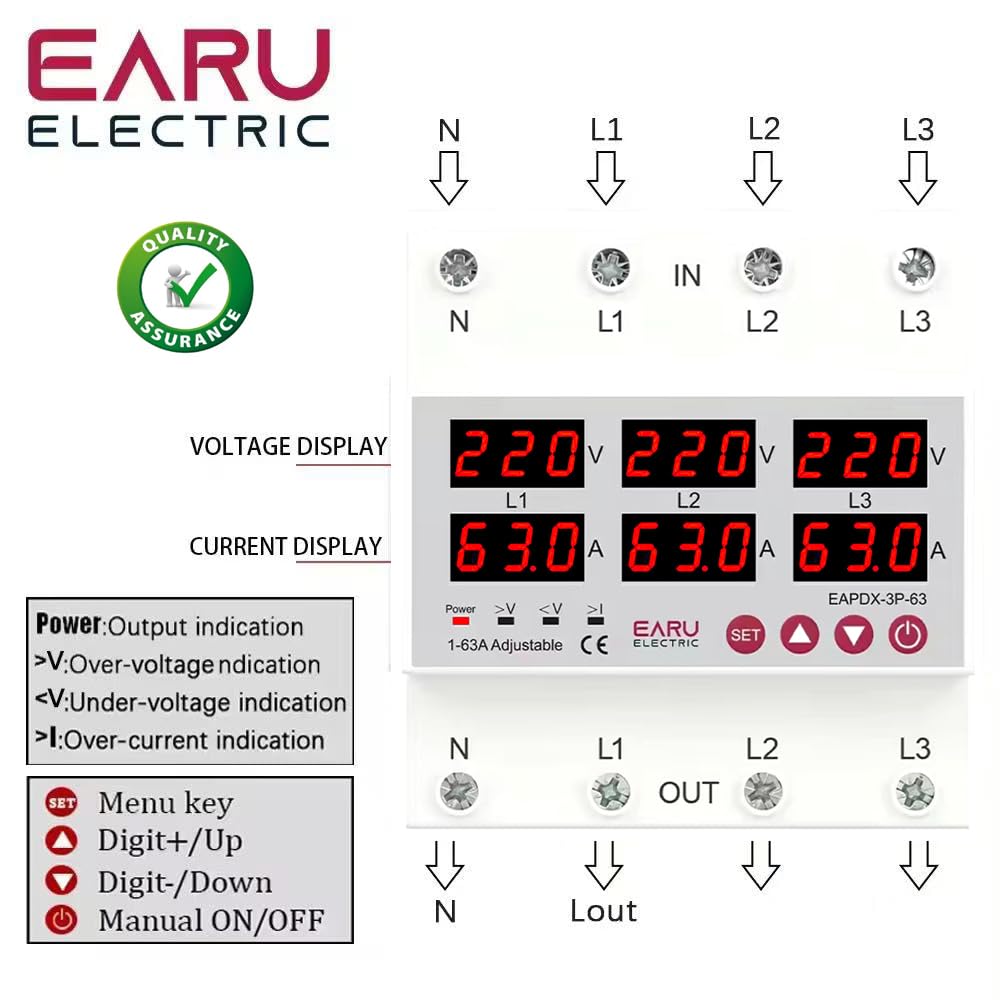
Image 3.2.1: Front view of the EARU Electric Voltage Protector, showing the LED display for L1, L2, L3 voltage and current, along with control buttons (SET, Up, Down, Power) and protection indicators. Terminal labels for N, L1, L2, L3 (IN and OUT) are also visible.

Image 3.2.2: A perspective view highlighting the product features and the input/output terminals (N, L1, L2, L3) at the top and bottom of the device. This image emphasizes the physical layout and connection points.
4. Setup and Installation
4.1. Mounting
The EARU-1008 is designed for DIN rail mounting. Securely attach the device to a standard 35mm DIN rail within an electrical enclosure.
4.2. Wiring Connections
Refer to the wiring diagram below for correct connections. Ensure all connections are tight and properly insulated.
- Connect the incoming neutral (N) and phase lines (L1, L2, L3) to the 'IN' terminals.
- Connect the outgoing neutral (N) and phase lines (L1, L2, L3) to the 'OUT' terminals.
- Double-check all connections before applying power.

Image 4.2.1: Detailed wiring diagram for the EARU Electric Voltage Protector, showing connections for N, L1, L2, L3 for both input and output. The diagram illustrates how to integrate the protector into a 3-phase electrical system.
5. Operating Instructions
5.1. Initial Power-Up
Once wired, apply power to the device. The LED display will illuminate, showing the real-time voltage and current for each phase.
5.2. Display Indicators
- V: Voltage display.
- A: Current display.
- Power: Output indication.
- >V: Over-voltage indication.
- <V: Under-voltage indication.
- >I: Over-current indication.
5.3. Setting Parameters
Use the 'SET' button to enter the configuration menu and the 'Up' and 'Down' keys to adjust values. Press 'SET' again to confirm and move to the next parameter. Hold 'SET' for 3 seconds to enter settings mode.

Image 5.3.1: A detailed guide to setting various protection parameters on the EARU Electric Voltage Protector. This includes overvoltage, undervoltage, overcurrent, and recovery delay settings, with default values and adjustment ranges.
Key adjustable parameters include:
- Overvoltage Protection Setting: Range 230-300V (Default 270V).
- Overvoltage Protection Recover Setting: Range 225-295V (Default 265V).
- Overvoltage Recovery Delay: Range 1-500s (Default 30s).
- Overvoltage Trip Delay: Range 0.1-30s (Default 1.0s).
- Undervoltage Protection Setting: Range 140-210V (Default 170V).
- Undervoltage Protection Recover Setting: Range 145-215V (Default 175V).
- Undervoltage Trip Delay: Range 0.1-30s (Default 1.0s).
- Overcurrent Protection Setting: Range 1-63A (Default 30A).
- Overcurrent Trip Delay: Range 0.1-30s (Default 1.0s).
- Voltage & Current Manual Error Calibration: Adjust for accuracy, range -9.5% to +9.5% (Default 0%).
- Power-on Delay Setting: Adjustable Range: 1-500S (Default: 10s).
5.4. Manual ON/OFF
The power button allows for manual switching of the device output.
6. Maintenance
The EARU-1008 is designed for minimal maintenance. However, periodic checks are recommended:
- Keep the device clean and free from dust and debris.
- Periodically inspect wiring connections for tightness and signs of wear.
- Ensure adequate ventilation around the device to prevent overheating.
7. Troubleshooting
If the device is not functioning as expected, consider the following:
- No Display/No Power: Check the main power supply and all wiring connections.
- Protection Trip: Identify the active protection indicator (>V, <V, >I). Check the corresponding voltage or current levels. The device will automatically reset once conditions return to normal, based on configured recovery delays.
- Phase Failure: The device automatically detects and responds to phase failures, initiating a cut-off and auto-reset once the phase is restored.
- Incorrect Readings: If readings appear inaccurate, consider performing a manual error calibration as described in Section 5.3.
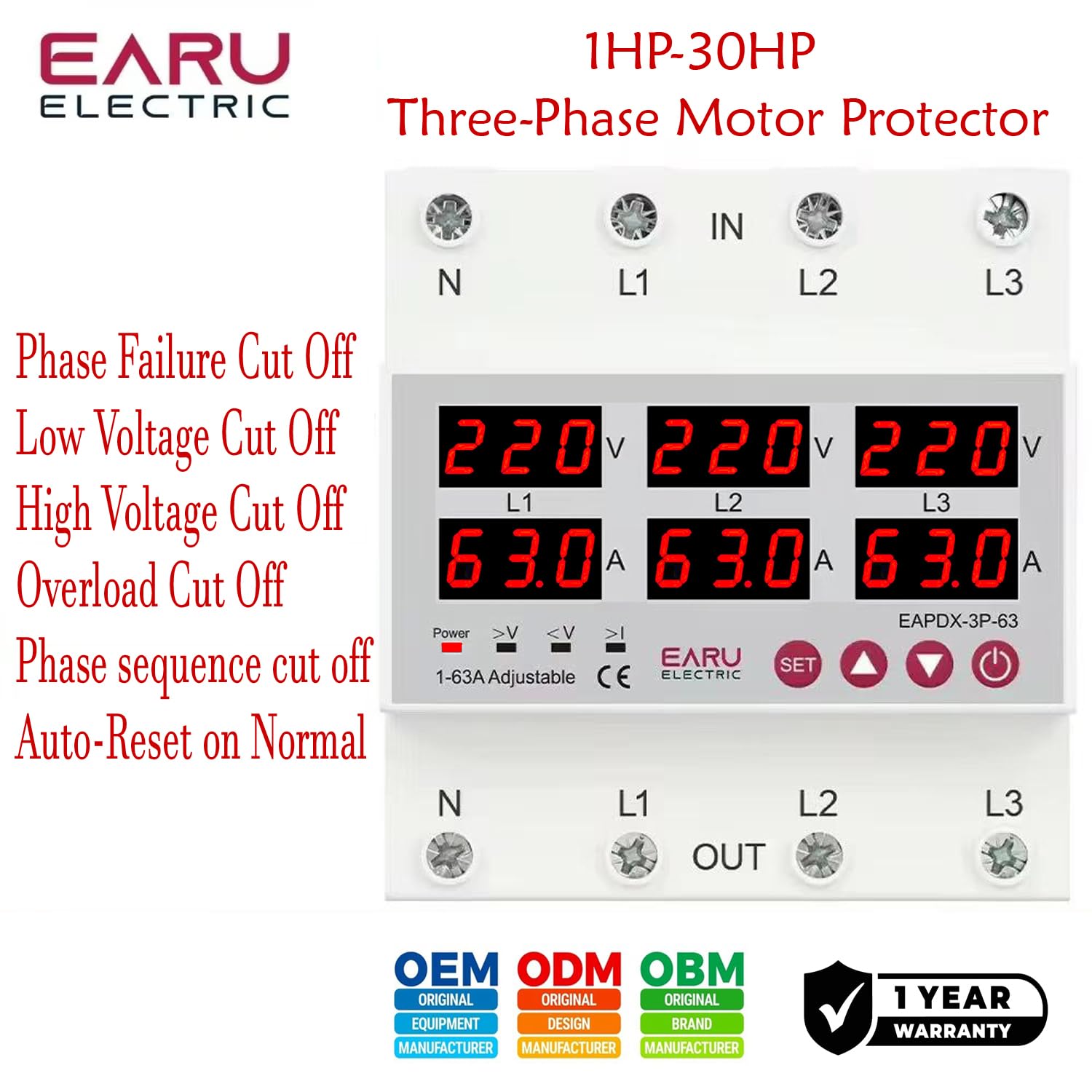
Image 7.1: This image highlights the various protection features of the EARU Electric Voltage Protector, including phase failure cut-off, low voltage cut-off, high voltage cut-off, overload cut-off, phase sequence cut-off, and auto-reset on normal conditions. These are key aspects for troubleshooting protection trips.
8. Specifications
| Parameter | Value |
|---|---|
| Brand | EARU |
| Model | EARU-1008 |
| Rated Supply Voltage | AC 3*220V (N-L1/L2/L3) / 440V |
| Rated Frequency | 50/60Hz |
| Over Current Protection Setting Range | 1-63A (Default 30A) |
| Over Voltage Protection Setting Range | 230-300V (Default 270V) |
| Under Voltage Protection Setting Range | 140-210V (Default 170V) |
| Product Dimensions | 20 x 10 x 20 cm |
| Item Weight | 450 g |
| Mounting Type | DIN Rail |

Image 8.1: This image provides a visual representation of the EARU Electric Voltage Protector's dimensions and a table of key technical specifications, including voltage, frequency, and protection ranges.
9. Warranty and Support
9.1. Warranty
The EARU Electric Voltage Protector (Model EARU-1008) comes with a 1-year manufacturer's warranty from the date of purchase, covering defects in materials and workmanship under normal use. Please retain your proof of purchase for warranty claims.
9.2. Customer Support
For technical assistance, troubleshooting, or warranty inquiries, please contact EARU customer support through your retailer or the official EARU website. Provide your model number (EARU-1008) and a detailed description of the issue for efficient service.


