1. Introduction
This manual provides essential information for the safe and efficient operation of your Anern 4200W Hybrid Solar Inverter. Please read this manual thoroughly before installation and use. Keep it for future reference.
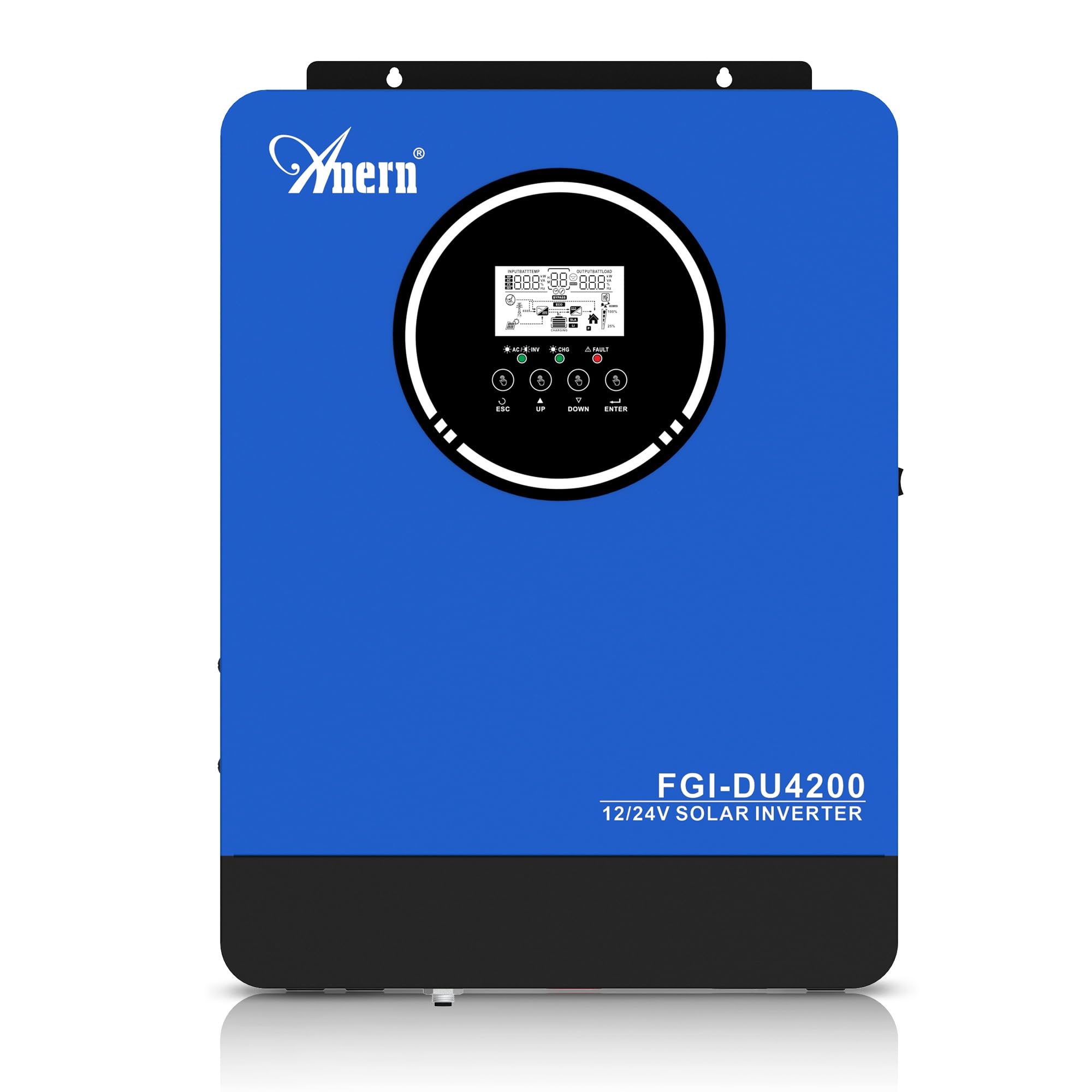
Figure 1: Anern 4200W Hybrid Solar Inverter. This image displays the main unit of the inverter, highlighting its key specifications such as 100A AC charging current, 4200W rated output power, and 500 VDC maximum PV array voltage.
2. Safety Instructions
Always observe the following safety precautions to reduce the risk of electric shock, fire, or injury:
- Installation must be performed by qualified personnel.
- Ensure all wiring is correctly connected and equipped with appropriate protective switches.
- Do not disassemble the inverter. There are no user-serviceable parts inside.
- Avoid exposing the inverter to rain, snow, spray, or any liquids.
- Ensure adequate ventilation around the inverter to prevent overheating.
- Disconnect all power sources (PV, battery, utility) before performing any maintenance or wiring.
3. Product Overview
The Anern 4200W Hybrid Solar Inverter is designed to convert DC power from solar panels and batteries into AC power for household use. It features an integrated 100A MPPT solar charge controller and supports both 12V and 24V battery systems with automatic detection.
Key Features:
- 4200W Pure Sine Wave Output: Provides stable and clean power for sensitive electronics.
- 100A MPPT Solar Charge Controller: Maximizes power harvest from solar panels.
- 12V/24V Battery Auto-Detection: Automatically adjusts output based on connected battery voltage.
- BMS Interface: Supports communication with lithium batteries for enhanced monitoring and protection.
- Real-time LED Display: Shows system status, operating data, and error codes.
- Configurable Charging & Output Modes: Offers flexibility for various application needs.
- Optional WiFi/GPRS Monitoring: Remote monitoring capability (module sold separately).

Figure 2: Inverter Display and Controls. This image illustrates the inverter's LCD display, function buttons for configuration, and the optional WiFi module for remote monitoring.
4. Setup and Installation
4.1 Wiring Diagram
Refer to the electrical schematic for proper system wiring. Ensure all connections are secure and correctly polarized.

Figure 3: Electrical Schematic. This diagram shows the complete wiring for a solar inverter system, including solar panels, combiner box, DC/AC breakers, inverter, utility grid connection, and loads.
4.2 Battery Connection
The inverter supports 12V and 24V battery configurations. It automatically detects the battery voltage and adjusts its output accordingly (2300W for 12V, 4200W for 24V). For 24V systems, connect two 12V batteries in series. For 12V systems, connect batteries in parallel if increasing capacity.

Figure 4: Battery Connection Options. This image illustrates how to connect batteries for 12V (parallel connection for 2300W output) and 24V (series connection for 4200W output) systems.
The inverter also supports lithium batteries and includes a BMS (Battery Management System) interface for monitoring and protection. Ensure the BMS is properly connected if using lithium batteries.

Figure 5: Communication Interfaces. This image highlights the dual communication interfaces for BMS (Battery Management System) and optional WiFi module, enabling remote monitoring and battery communication.
4.3 Startup and Shutdown Sequence
Startup Sequence:
- Connect the battery.
- Turn on the inverter.
- Activate the protective switches for PV, Utility, and Loads.
Shutdown Sequence:
- Deactivate the protective switches for Loads, Utility, and PV.
- Turn off the inverter.
- Disconnect the battery.
Important Note: Inductive loads (e.g., motors, refrigerators) may require up to 3 times their rated power for startup. Ensure the inverter's capacity is sufficient to handle these surge loads. Exceeding the inverter's surge capacity can cause damage.
5. Operation
5.1 LCD Display and Settings
The inverter features an LED display that provides real-time system data and operating status. Use the function buttons below the display to navigate menus and configure settings. Settings include battery charging current, AC/solar charging priority, and charging current priority.
5.2 Charging Modes
The inverter offers four configurable charging modes:
- Solar Priority: Solar power is prioritized for charging.
- Solar Only: Only solar power is used for charging.
- Utility Priority: Utility grid power is prioritized for charging.
- Solar + Utility Hybrid: Combines solar and utility power for charging.
5.3 Output Modes
Three output modes are available to adapt to various application needs:
- Solar Priority (SUB): Solar power is prioritized for loads.
- Utility Priority (USB): Utility grid power is prioritized for loads.
- SBU: Solar, Battery, Utility priority.

Figure 6: Charging and Output Modes. This diagram visually explains the four available charging modes (Solar Charge, Utility Priority, Solar Priority, Hybrid Charge) and three load output modes (PV Priority, Utility Priority, SBU Priority).
5.4 Remote Monitoring
The inverter supports remote monitoring via an optional WiFi/GPRS module (sold separately). This allows users to monitor system performance and status from a distance.
6. Maintenance
Regular maintenance ensures optimal performance and longevity of your inverter:
- Keep the inverter clean and free from dust. Use a dry cloth for cleaning.
- Ensure ventilation openings are not blocked.
- Periodically check all wiring connections for tightness and signs of corrosion.
- Monitor the battery status, especially if using lithium batteries with the BMS interface, to prevent overcharge or deep discharge.
- Inspect solar panels for dirt or damage that could reduce efficiency.
7. Troubleshooting
The LED display will show error codes if issues arise. Refer to the inverter's display for specific error codes to diagnose and resolve problems. Common issues and their potential solutions include:
- No Power Output: Check battery connections, DC/AC breakers, and inverter power switch.
- Low Battery Voltage: Ensure batteries are adequately charged. Check charging sources (solar, utility).
- Overload Warning: Reduce the connected load. Inductive loads may cause temporary overloads during startup.
- Overheating: Ensure proper ventilation. Clean any dust from the inverter's vents.
- PV Input Error: Check solar panel connections and voltage. Ensure PV array voltage is within the specified range (55-500V DC).
For persistent issues or error codes not listed, contact customer support.
8. Technical Specifications
| Feature | Specification |
|---|---|
| Brand | Anern |
| Model Number | AN-FGI-DU 4200 |
| Electrical Power | 4200 Watts |
| Output Power | 4500 Watts |
| Max. Output Power (Watts) | 4200 |
| Output Waveform | Pure Sine Wave |
| Power Source | Solar Powered, Battery Powered |
| Recommended Product Uses | Home |
| Included Components | Instruction Manual |
| Compliance | CE |
| Product Dimensions | 30 x 10 x 40 cm; 8.86 kg |
9. Warranty and Support
For warranty information and technical support, please refer to the documentation provided with your purchase or contact Anern customer service. Keep your purchase receipt as proof of purchase.