1. Introduction
This manual provides detailed instructions for the installation, operation, and maintenance of the SIMAIR SEO1602-A 2.34 inch 16x2 Character OLED Display Module. This module is designed for various embedded applications requiring a compact and clear character display.

Figure 1: Front view of the SIMAIR SEO1602-A OLED Display Module.
2. Key Features
- 2.34 inch diagonal display size.
- 16 characters by 2 lines display format.
- OLED technology for high brightness and contrast.
- Monochrome white character display.
- Supports multiple communication interfaces: 6800/8080 Parallel, SPI, and IIC.
- Integrated SSD1311 controller chip.
- COB (Chip-on-Board) package for compact design.
- Wide operating temperature range: -40°C to 80°C.
- 16-pin interface for connectivity.
- Constructed with ROHS compliant environmental protection materials.
3. Specifications
| Feature | Value |
|---|---|
| Display Type | OLED Character Display |
| Display Format | 16 Characters x 2 Lines |
| Screen Size | 2.34 inches |
| Display Color | Monochrome White |
| Controller IC | SSD1311 |
| Communication Interfaces | 6800/8080 Parallel, SPI, IIC |
| Operating Temperature | -40°C to 80°C |
| Number of Pins | 16 |
| Product Dimensions (W x H x D) | 80.0mm x 36.0mm x 9.4mm (approx.) |
| Response Time | 2 Milliseconds |
| Aspect Ratio | 2.22:1 |
| Manufacturer | SIMAIR |
| Model Number | SEO1602-A |
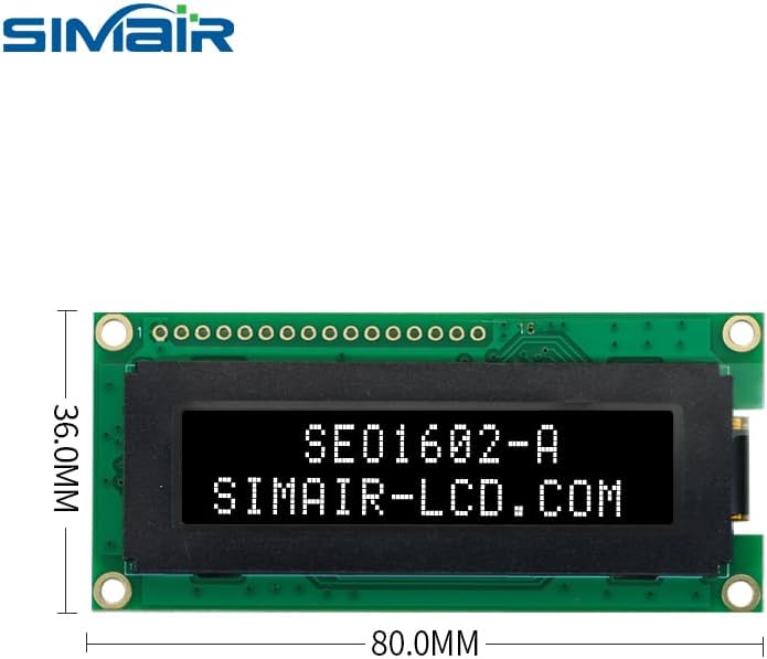
Figure 2: Dimensions of the SIMAIR SEO1602-A OLED Display Module.
4. Pinout Description
The SEO1602-A module features a 16-pin interface for power, data, and control signals. The specific function of each pin depends on the chosen communication mode (Parallel, SPI, or IIC). Users should refer to the detailed datasheet for the SSD1311 controller and the module for precise pin assignments and electrical characteristics.

Figure 3: Back view of the SIMAIR SEO1602-A OLED Display Module, illustrating the PCB and pin interface.
5. Setup and Installation
5.1. Power Supply
Ensure the correct voltage is supplied to the module as specified in the datasheet. Incorrect voltage can lead to irreversible damage to the display module. Typically, these modules operate on a 3.3V or 5V supply, but always verify with the official documentation.
5.2. Interface Connection
Connect the module to your microcontroller or system board using the appropriate communication interface (6800/8080 Parallel, SPI, or IIC). Verify all pin connections are secure and correct according to the chosen interface protocol. Pay close attention to data lines, clock lines, and control signals (e.g., CS, DC, RES for SPI/IIC, or RS, RW, E for Parallel).
5.3. Initializing the Display
After power-up, the display requires a specific sequence of initialization commands sent via the chosen communication interface. Consult the SSD1311 controller datasheet or example code provided by SIMAIR or the controller manufacturer for the precise initialization sequence. This sequence typically sets up display mode, contrast, and other operational parameters.
6. Operating Instructions
6.1. Displaying Characters
Characters are displayed by sending their ASCII values to the display's data registers. The SSD1311 controller handles character mapping and display refreshing. Ensure your character data is formatted correctly for the selected communication mode.
6.2. Cursor Control
The display supports cursor positioning and visibility control. Commands are available to move the cursor to a specific character position (row and column) and to turn the cursor on/off. Refer to the SSD1311 datasheet for the specific command codes.
6.3. Brightness Adjustment
The SSD1311 controller may offer commands for adjusting the display's brightness or contrast. These settings can be modified by sending specific commands to the controller. Consult the controller datasheet for detailed register settings and command structures.
7. Maintenance
- Keep the display surface clean and free from dust and moisture. Use a soft, dry, lint-free cloth for cleaning. Avoid abrasive materials or chemical cleaners.
- Avoid applying excessive pressure to the display area, as this can damage the OLED panel.
- Store the module in a dry, anti-static environment when not in use to prevent electrostatic discharge (ESD) damage.
- Do not expose the module to extreme temperatures outside its specified operating range (-40°C to 80°C) or to direct sunlight for prolonged periods.
8. Troubleshooting
8.1. Display Not Lighting Up
- Check power supply connections and voltage levels to ensure they are within the specified range.
- Verify all interface connections are correct and secure. Loose connections are a common cause of display issues.
- Ensure the display initialization sequence has been sent correctly and completely after power-up.
8.2. Incorrect Characters Displayed
- Confirm the correct communication protocol (Parallel, SPI, IIC) is selected and implemented in your code.
- Check the data being sent to the display for accuracy. Ensure ASCII values correspond to the desired characters.
- Verify the character set and font settings if applicable, especially if using custom characters.
8.3. Intermittent Display
- Inspect for loose connections or cold solder joints on the module or connecting wires.
- Check for electromagnetic interference (EMI) in the operating environment that might disrupt communication.
- Ensure the power supply is stable and free from noise.
9. Warranty and Support
This product is covered by the manufacturer's standard warranty against defects in materials and workmanship. For technical support, detailed datasheets, or warranty claims, please contact your vendor or refer to the official SIMAIR website for the most up-to-date information and resources.


