1. Introduction
The GOLDCHAMP GC-T0-TS68 Megohmmeter Insulation Resistance Tester is a versatile and robust instrument designed for precise measurements of AC/DC voltage and insulation resistance. It features a wide measurement range, data storage capabilities, and automatic calculation functions for Polarization Index (PI) and Dielectric Absorption Ratio (DAR). This manual provides essential information for safe and effective use of the device.
2. Safety Information
Always adhere to safety precautions when operating electrical testing equipment. Failure to do so may result in injury or damage to the device. This device is designed with smart auto-discharge and low battery warnings to enhance user safety.
- Ensure the device is turned off before connecting or disconnecting test leads.
- Do not use the device if it appears damaged or is operating abnormally.
- Verify the correct voltage range is selected for the measurement being performed.
- Avoid contact with live circuits during testing.
- Replace batteries promptly when low battery warning is displayed.
3. Setup
3.1. Unboxing and Components
Carefully unpack the GOLDCHAMP GC-T0-TS68 Megohmmeter and verify all components are present. The standard package includes:
- 1 x GOLDCHAMP GC-T0-TS68 Megohmmeter
- 1 x Black Storage Bag
- 1 x Instruction Manual
- 8 x AA Batteries (Note: Batteries may not be included in all packages. Please check product description.)
- 1 x Pair of Meter Pens (Test Leads)
- 1 x Pair of Crocodile Clips
- 1 x Small Screwdriver
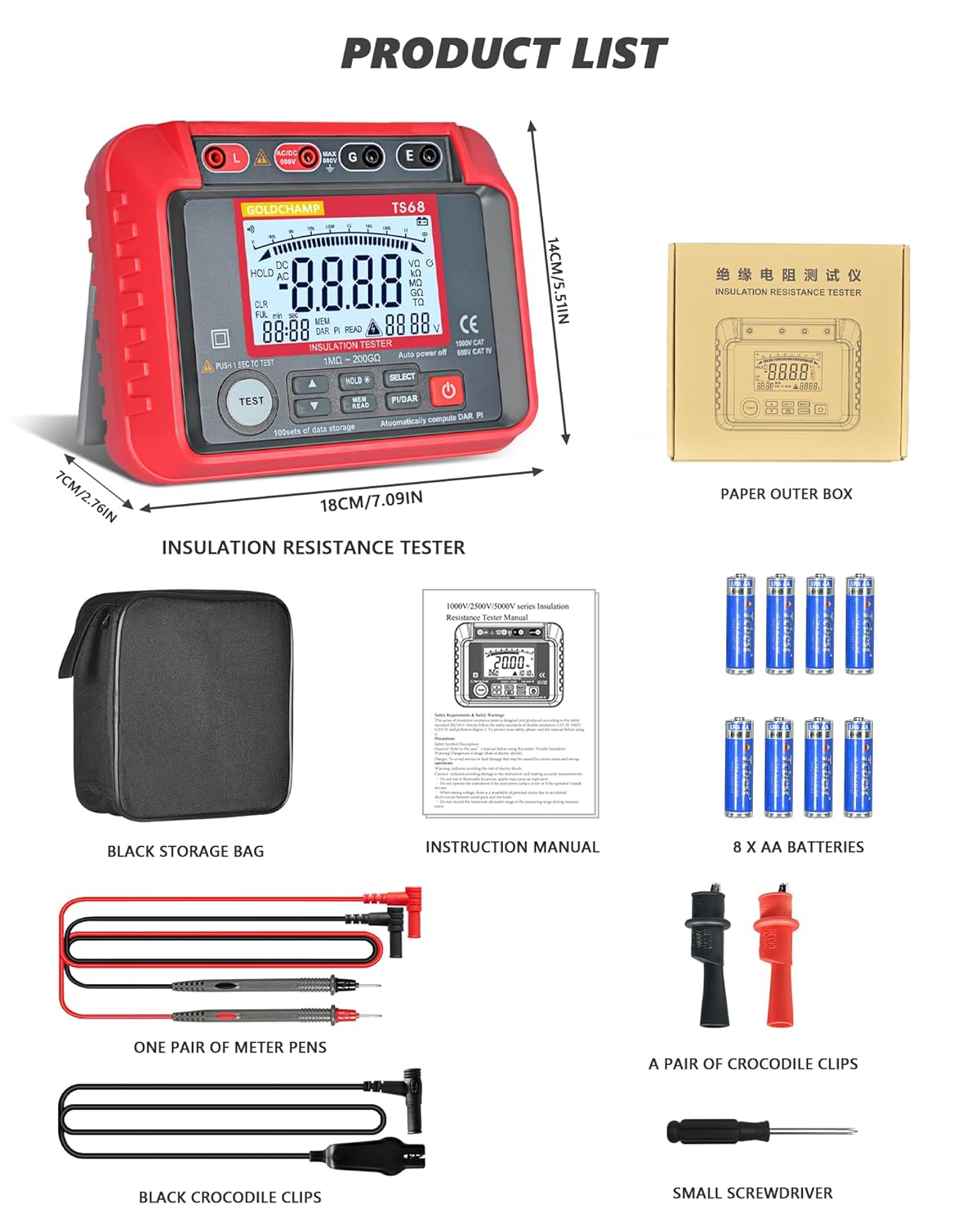
Figure 3.1: Contents of the GOLDCHAMP GC-T0-TS68 package, including the megohmmeter, storage bag, instruction manual, batteries, test leads, crocodile clips, and a small screwdriver.
3.2. Battery Installation
The device requires 8 AA batteries for operation. To install or replace batteries:
- Ensure the device is powered off.
- Locate the battery compartment cover on the back of the device.
- Use the provided small screwdriver to loosen the screw(s) securing the battery cover.
- Remove the cover and insert 8 AA batteries, observing the correct polarity (+/-) as indicated inside the compartment.
- Replace the battery cover and tighten the screw(s).

Figure 3.2: The battery compartment of the megohmmeter, showing the placement of AA batteries.
4. Operating Instructions
4.1. Device Overview and Controls
Familiarize yourself with the various parts and controls of the GC-T0-TS68 Megohmmeter for effective operation.

Figure 4.1: Detailed view of the megohmmeter's panel, highlighting key components such as the LCD display, output jacks, measurement terminals, and control buttons.
- Output Jack L: Live output terminal.
- Measurement Positive Terminal: Positive input for measurements.
- Input Negative Shield G: Ground/Shield terminal.
- Sampling Jack E: Earth terminal for insulation resistance.
- Liquid Crystal Display (LCD): Displays measurement results and settings.
- High Voltage Start Button (TEST): Initiates insulation resistance test.
- UP Button: Navigates menus or increases values.
- DOWN Button: Navigates menus or decreases values.
- Data Hold/Backlight Button (HOLD): Freezes current display; long press activates/deactivates backlight.
- Data Read/Save Button (MEM/READ): Accesses stored data or saves current data.
- Function Selection Button (SELECT): Cycles through measurement functions.
- Polarization Index (PI) / Dielectric Absorption Ratio (DAR) Button (PI/DAR): Initiates PI/DAR calculations.
- Power ON/OFF Button: Turns the device on or off.
4.2. Measuring AC/DC Voltage
The GC-T0-TS68 can measure AC/DC voltage from 10V to 600V.
- Connect the red test lead to the "Measurement Positive Terminal" and the black test lead to the "Input Negative Shield G" or "Sampling Jack E" for voltage measurements.
- Turn on the device using the Power ON/OFF button.
- Use the Function Selection Button to select the ACV or DCV mode.
- Carefully connect the test leads to the circuit or component to be measured.
- Read the voltage value displayed on the LCD.
4.3. Measuring Insulation Resistance
This device measures insulation resistance from 1 MΩ to 200 GΩ with multiple test voltages (250V-2500V).
- Ensure the circuit or equipment under test is de-energized and safely discharged before connecting the megohmmeter.
- Connect the red test lead to the "Output Jack L" and the black test lead to the "Sampling Jack E" or "Input Negative Shield G" depending on the test setup.
- Turn on the device.
- Use the Function Selection Button to select the desired insulation resistance test voltage (e.g., 250V, 500V, 1000V, 2500V).
- Press and hold the High Voltage Start Button (TEST) to initiate the test. The high voltage indicator will light up.
- Read the insulation resistance value on the LCD. Release the TEST button to stop the test. The device features automatic discharge after the test.

Figure 4.2: The megohmmeter connected to electrical equipment for an insulation resistance test.

Figure 4.3: The megohmmeter connected to a pipe for an insulation resistance test.

Figure 4.4: The megohmmeter connected to a power plug for an insulation resistance test.
4.4. PI and DAR Calculations
The device automatically calculates Polarization Index (PI) and Dielectric Absorption Ratio (DAR) to assess insulation health.
- Perform an insulation resistance test as described above.
- Press the PI/DAR button. The device will automatically perform the necessary measurements over time and display the calculated PI and DAR values.
4.5. Data Storage and Recall
The GC-T0-TS68 can store up to 100 sets of measurement data.
- After a measurement, press the HOLD button to freeze the display.
- Press the MEM/READ button to save the current data.
- To recall stored data, press the MEM/READ button repeatedly to cycle through the stored records.

Figure 4.5: Illustration of the data storage and recall feature, showing multiple data sets on the display.
4.6. Backlight Function
The high-contrast backlight display enhances usability in low-light conditions.
- To activate the backlight, press and hold the HOLD button.
- To deactivate the backlight, press and hold the HOLD button again.

Figure 4.6: The megohmmeter displaying a clear, backlit screen for improved visibility.
5. Maintenance
Proper maintenance ensures the longevity and accuracy of your GOLDCHAMP GC-T0-TS68 Megohmmeter.
- Cleaning: Wipe the device with a dry, soft cloth. Do not use abrasive cleaners or solvents.
- Storage: Store the device in its durable carrying case in a cool, dry place when not in use. Remove batteries if storing for extended periods to prevent leakage.
- Physical Protection: The device features shockproof silicone armor and a double-insulated casing. While designed to withstand drops and rough handling, avoid unnecessary impacts to maintain optimal performance.

Figure 5.1: The megohmmeter's robust design with silicone shock protection.
6. Troubleshooting
If you encounter issues with your GC-T0-TS68 Megohmmeter, refer to the following common troubleshooting steps:
| Problem | Possible Cause | Solution |
|---|---|---|
| Device does not power on. | Dead or incorrectly installed batteries. | Check battery polarity and replace with fresh AA batteries. |
| Inaccurate readings. | Poor connection of test leads; incorrect measurement mode selected; external interference. | Ensure test leads are securely connected. Verify the correct function (ACV/DCV/Insulation) is selected. Move away from strong electromagnetic fields. |
| "OL" or "OVER" displayed. | Measurement exceeds the device's range. | Ensure the measured value is within the specified range for the selected test voltage. |
| High voltage warning (HV) remains on after test. | Residual charge in the circuit. | The device has an auto-discharge function. Wait for the HV indicator to turn off before disconnecting leads. If it persists, ensure the circuit is safely discharged manually. |
If the problem persists after attempting these solutions, please contact customer support.
7. Specifications
Key technical specifications for the GOLDCHAMP GC-T0-TS68 Megohmmeter:
| Feature | Detail |
|---|---|
| Brand | GOLDCHAMP |
| Model Number | GCCA-T0-TS68 |
| Insulation Resistance Range | 1 MΩ - 200 GΩ |
| Output Voltage (Insulation Test) | 250V, 500V, 1000V, 2500V (Multiple test voltages) |
| AC/DC Voltage Measurement | 10V - 600V |
| Data Storage | 100 sets |
| Display | Backlight LCD Display |
| Special Features | Automatic PI & DAR calculations, Data Hold, Auto Power-Off, Smart Auto-Discharge, Low Battery Warning, 45° Stand, Shockproof Silicone Armor, Double-Insulated Casing |
| Power Source | Battery Powered (8 x AA batteries) |
| Item Weight | 798 g |
| Parcel Dimensions | 17.98 x 14 x 6.99 cm |
| Measurement Accuracy | +/-0.5% |
| Min. Operating Voltage | 10 Volts |
| Upper Temperature Rating | 35 Degrees Celsius |
| Country of Origin | China |
8. Warranty & Support
For warranty information and customer support, please refer to the documentation included with your product or contact GOLDCHAMP customer service directly. Keep your purchase receipt as proof of purchase.
- Warranty Period: Please check your product packaging or the official GOLDCHAMP website for specific warranty terms.
- Customer Support: For technical assistance, troubleshooting, or service inquiries, contact GOLDCHAMP customer support through their official channels.


