1. Introduction
The ETCR2000A Digital Clamp Ground Resistance Tester is a specialized instrument designed for measuring grounding resistance in various electrical systems. This device offers a non-intrusive method for testing loop resistance without the need to disconnect grounding leads or use auxiliary electrodes, making it suitable for applications in power systems, meteorology, oilfields, construction, and industrial electrical equipment.
It accurately measures the combined resistance of the grounding body and lead, and is capable of detecting ground faults that traditional methods may miss. This manual provides detailed instructions for the safe and effective use of your ETCR2000A tester.
2. Safety Information
WARNING: Read all safety warnings and instructions before using this product. Failure to follow the warnings and instructions may result in electric shock, fire, or serious injury.
- Always observe local and national safety regulations.
- Do not use the instrument if it appears damaged or operates abnormally.
- Ensure the instrument is clean and dry before use.
- Do not exceed the maximum input ratings for any function.
- Always disconnect the instrument from the circuit before opening the battery compartment.
- This device is designed to measure loop resistance only, not single-point grounding. For single-point grounding, an artificial loop must be created.
3. Package Contents
Verify that all items listed below are present and in good condition:
- ETCR2000A Digital Clamp Ground Resistance Meter
- Test Ring
- User Manual
- LR6 Battery (AA, 1.5V) x 4
- Carrying Case

Image: The ETCR2000A kit, showing the clamp meter, test ring, user manual, batteries, and protective carrying case.
4. Product Overview
The ETCR2000A features an intuitive design for ease of use. Familiarize yourself with the main components:

Image: Front view of the ETCR2000A, showing the display, clamp jaws, and control buttons.

Image: Side view of the ETCR2000A, illustrating the clamp opening mechanism and the jaw size.

Image: Close-up of the clamp jaws, highlighting the internal voltage and current coils for measurement.

Image: Key features of the ETCR2000A, including its resistance range, resolution, clamp jaw size, and data memory capacity.
5. Setup
5.1 Battery Installation
- Ensure the device is powered off.
- Locate the battery compartment on the back of the unit.
- Use a screwdriver to open the battery compartment cover.
- Insert four LR6 (AA, 1.5V) batteries, observing the correct polarity (+/-).
- Replace the battery compartment cover and secure it with the screw.
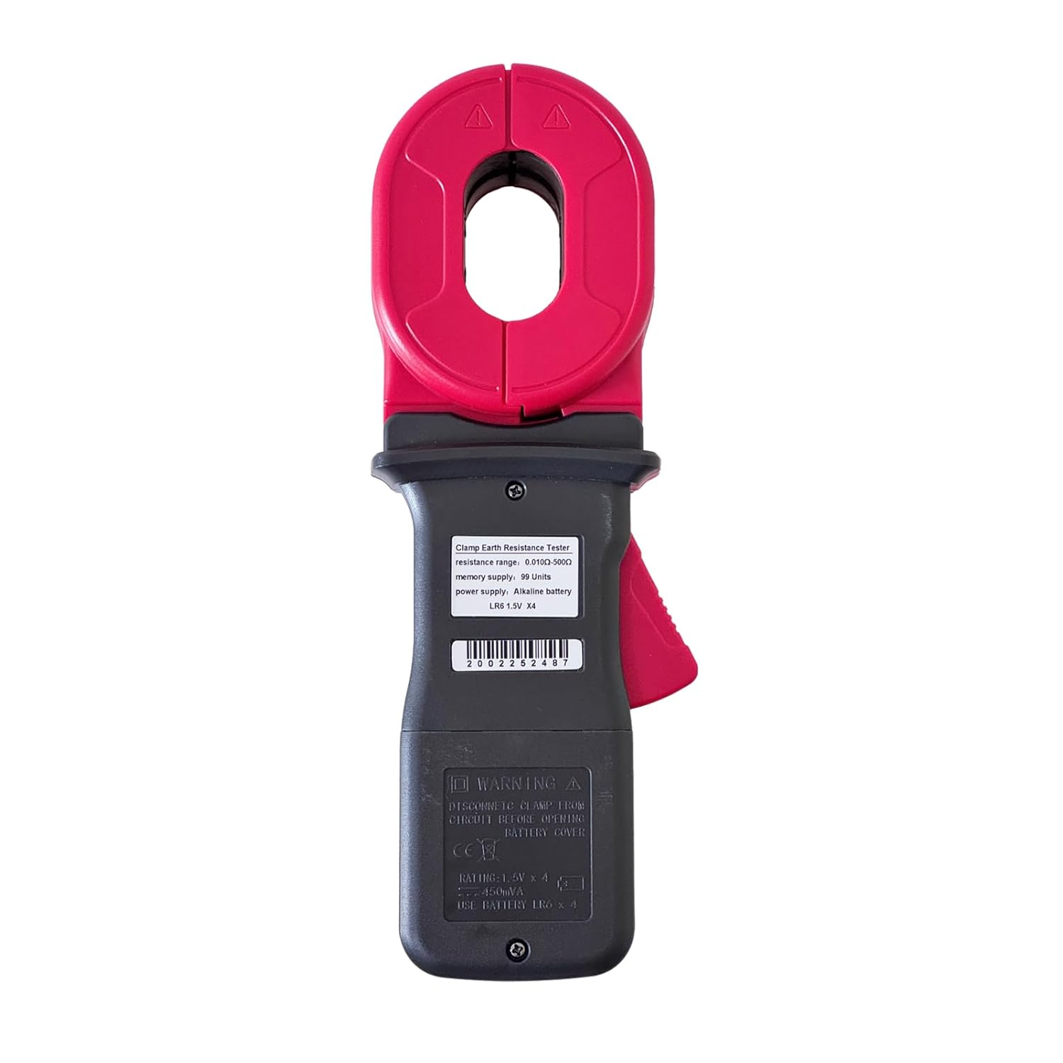
Image: Rear view of the ETCR2000A, indicating the location of the battery compartment.
6. Operating Instructions
6.1 Powering On/Off
Press the POWER button to turn the device on or off.
6.2 Taking a Measurement (Loop Resistance)
The ETCR2000A is designed for loop resistance measurement. It measures induced potential and current to calculate resistance using the formula R=E/I.
- Ensure the circuit to be tested forms a closed loop. The tester cannot measure single-point grounding directly. If testing a single grounding electrode, an artificial loop must be created (e.g., by connecting a temporary conductor to another known ground point or using the provided test ring).
- Open the clamp jaws by pressing the lever.
- Place the clamp around the grounding conductor or loop to be measured. Ensure the jaws are fully closed and there are no gaps.
- The resistance value will be displayed on the LCD screen.
- For stable readings, hold the clamp steady during measurement.
6.3 Data Hold Function
Press the HOLD button to freeze the current reading on the display. Press it again to release the hold function.
6.4 Mode Selection
The MODE button may be used to cycle through different measurement modes or display options if available. Refer to the on-screen indicators.

Image: The ETCR2000A display showing 'OL' (Open Loop), which indicates the circuit is not closed or the resistance is out of range.
7. Maintenance
7.1 Cleaning
Wipe the instrument with a dry, soft cloth. Do not use abrasive cleaners or solvents. Ensure no moisture enters the device.
7.2 Battery Replacement
When the low battery indicator appears on the display, replace the batteries as described in the 'Battery Installation' section (5.1).
7.3 Storage
Store the instrument in its carrying case in a cool, dry place, away from direct sunlight and extreme temperatures. Remove batteries if the device will not be used for an extended period.
8. Troubleshooting
| Problem | Possible Cause | Solution |
|---|---|---|
| No display or weak display | Dead or low batteries | Replace batteries. |
| "OL" (Open Loop) displayed | Circuit is not a closed loop; clamp jaws not fully closed; resistance is out of range. | Ensure the circuit forms a complete loop. Check that the clamp jaws are fully closed around the conductor. Verify the resistance is within the 0.010Ω-500Ω range. |
| Inaccurate readings | Interference; dirty clamp jaws; improper contact. | Move away from strong electromagnetic fields. Clean the clamp jaws. Ensure good contact with the conductor. |
9. Specifications
| Parameter | Value |
|---|---|
| Model | ETCR2000A |
| Resistance Range | 0.010Ω - 500Ω |
| Resistance Resolution | 0.001Ω |
| Clamp Jaw Size | 55mm x 32mm |
| Opening Size | 32mm |
| Power Source | 4 x LR6 (AA) 1.5V Batteries |
| Minimum Operating Voltage | 6 Volts (DC) |
| Upper Temperature Rating | 55°C |
| Item Weight | 2.1 Pounds (approx. 0.95 kg) |
| Item Dimensions | 10.83 x 3.94 x 2.2 inches (approx. 27.5 x 10 x 5.6 cm) |
| Measurement Type | Ohmmeter (Loop Resistance) |
| Specification Met | CE |
| Memory Data | 99 Groups |
9.1 Accuracy
The ETCR2000A provides precise measurements. For the 50.0-99.5 Ohm range, the accuracy is typically ±1.5% + 0.5 Ohms. Accuracy may vary slightly across different ranges. Always ensure proper calibration and environmental conditions for optimal performance.
10. Applications
The ETCR2000A is suitable for a wide range of professional applications:
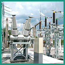
Image: Testing in power substations.

Image: Use on construction sites.
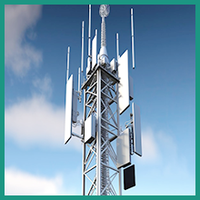
Image: Testing telecommunication towers.
11. Warranty and Support
For warranty information and technical support, please refer to the documentation provided with your purchase or contact ETCR customer service. Keep your purchase receipt as proof of purchase.


