1. Introduction
This manual provides essential information for the Dorman 528-101 Rear Lower Suspension Control Arm. This component is engineered to be a direct replacement for the original equipment on specific Infiniti and Nissan vehicles, ensuring proper fit and performance. It is manufactured to strict standards using durable materials and undergoes rigorous testing to ensure longevity and reliability.
The Dorman 528-101 is compatible with the following vehicle models:
- Infiniti JX35: 2013
- Infiniti QX60: 2014, 2015, 2016, 2017, 2018, 2019, 2020, 2021, 2022, 2023, 2024
- Nissan Pathfinder: 2013, 2014, 2015, 2016, 2017, 2018, 2019, 2020, 2021, 2022, 2023, 2024
Always verify fitment for your specific vehicle using a vehicle compatibility tool before installation.

Image 1.1: The Dorman 528-101 Rear Lower Suspension Control Arm, showing its overall design and construction.
2. Safety Information
Working on vehicle suspension systems can be hazardous. Always prioritize safety. It is highly recommended that installation be performed by a qualified automotive technician. If you choose to proceed with installation yourself, ensure you have the correct tools, follow all safety precautions, and consult a service manual specific to your vehicle.
- Wear appropriate personal protective equipment (PPE), including safety glasses and gloves.
- Ensure the vehicle is securely supported on jack stands on a level surface. Never rely solely on a jack.
- Disconnect the vehicle's battery before beginning work to prevent accidental electrical discharge.
- Use proper lifting techniques and tools to avoid injury.
- Be aware of potential hazards such as compressed springs, hot components, and sharp edges.
3. Installation
3.1 Required Tools and Materials
- Vehicle service manual (specific to your vehicle model)
- Jack and jack stands
- Wheel chocks
- Socket wrench set
- Torque wrench
- Pry bar
- Penetrating oil (optional, for rusted bolts)
- Wire brush (optional, for cleaning threads)
- New fasteners (if recommended by vehicle manufacturer)
3.2 General Installation Steps (Consult Vehicle Service Manual for Specifics)
- Prepare the Vehicle: Park the vehicle on a level surface, engage the parking brake, and place wheel chocks on the wheels that will remain on the ground. Loosen the lug nuts on the wheel(s) corresponding to the control arm being replaced.
- Lift and Secure: Safely lift the rear of the vehicle using a jack and support it securely with jack stands. Remove the wheel(s).
- Access the Control Arm: Locate the rear lower suspension control arm. It connects the wheel hub assembly to the vehicle's chassis.
- Remove Old Control Arm:
- Support the suspension assembly if necessary to relieve tension on the control arm.
- Remove the bolts securing the control arm to the chassis and the wheel hub assembly. Note the orientation of all components and fasteners.
- Carefully remove the old control arm.
- Install New Control Arm:
- Position the new Dorman 528-101 control arm into place.
- Insert the bolts, but do not fully tighten them yet. It is crucial to tighten suspension components with the vehicle's weight on the suspension (or at ride height) to prevent premature bushing wear.
- Final Tightening: Lower the vehicle partially or use a secondary jack to simulate ride height. Torque all control arm bolts to the specifications provided in your vehicle's service manual.
- Reassemble: Reinstall the wheel(s) and torque the lug nuts to factory specifications. Lower the vehicle completely.
- Post-Installation: It is highly recommended to have a professional wheel alignment performed after replacing any suspension components to ensure proper vehicle handling and tire wear.

Image 3.1: Dorman Chassis components, highlighting premium construction designed to meet or exceed OEM specifications.
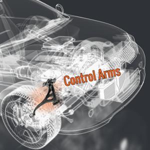
Image 3.2: Diagram illustrating the general location of a control arm within a vehicle's suspension system.
4. Function and Operation
The rear lower suspension control arm is a critical component of your vehicle's independent suspension system. Its primary functions include:
- Wheel Positioning: It maintains the correct alignment of the wheel relative to the vehicle's chassis, ensuring proper camber and toe angles.
- Load Bearing: It supports the weight of the vehicle and transfers forces from the wheel to the chassis during driving, braking, and cornering.
- Ride Comfort: Through its bushings, it helps absorb road shocks and vibrations, contributing to a smoother ride.
- Steering Response: A properly functioning control arm is essential for precise steering and stable handling.
The Dorman 528-101 is designed to restore these functions to original equipment specifications, ensuring your vehicle performs as intended.
5. Maintenance
Suspension components, including control arms, are subject to wear and tear over time. While the Dorman 528-101 is built for durability, regular inspection is recommended to ensure optimal performance and safety.
5.1 Inspection Schedule
- Inspect suspension components during routine oil changes or tire rotations (typically every 5,000-10,000 miles or 6-12 months).
- Perform an inspection immediately if you notice any changes in vehicle handling, unusual noises, or uneven tire wear.
5.2 What to Look For
- Bushing Condition: Check for cracks, tears, or excessive play in the rubber bushings at the pivot points. Worn bushings can lead to clunking noises and poor handling.
- Ball Joint (if applicable): Inspect the ball joint boot for tears and check for excessive play. (Note: This specific control arm appears to be a stamped steel arm with bushings, not necessarily an integrated ball joint, but general advice for control arms is useful).
- Component Damage: Look for any signs of bending, cracks, or corrosion on the control arm itself.
- Fastener Tightness: Ensure all mounting bolts are securely tightened.
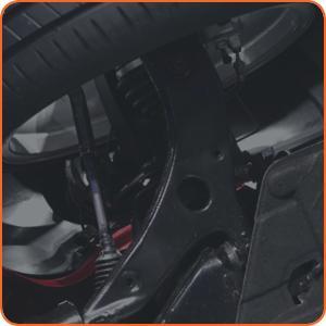
Image 5.1: A close-up view of vehicle suspension components, illustrating areas to inspect for wear or damage.
6. Troubleshooting Common Issues
If you experience any of the following symptoms after installation or during normal operation, it may indicate an issue with the suspension system, potentially including the control arm:
- Clunking or Popping Noises: Often heard when going over bumps or turning. This can indicate worn bushings, loose fasteners, or a faulty ball joint.
- Uneven Tire Wear: Can be a symptom of incorrect wheel alignment, which can be caused by worn suspension components.
- Poor Handling or Steering: Vehicle pulling to one side, loose steering, or difficulty maintaining a straight line can point to suspension issues.
- Vibrations: While often related to tires or wheels, worn suspension components can also contribute to vibrations felt through the steering wheel or chassis.
If you encounter any of these symptoms, it is crucial to have your vehicle inspected by a qualified technician immediately to diagnose the root cause and ensure safe operation.
7. Specifications
Key specifications for the Dorman 528-101 Rear Lower Suspension Control Arm:
| Attribute | Value |
|---|---|
| Brand | Dorman |
| Model Number | 528-101 |
| Part Type | Rear Lower Suspension Control Arm |
| Fit Type | Vehicle Specific Fit |
| Item Weight | 6.3 pounds |
| Product Dimensions | 23.25 x 17.75 x 5.87 inches |
| UPC | 889245076236 |
| OEM Part Number Cross-Reference | RK643348; 551B03JA0A |
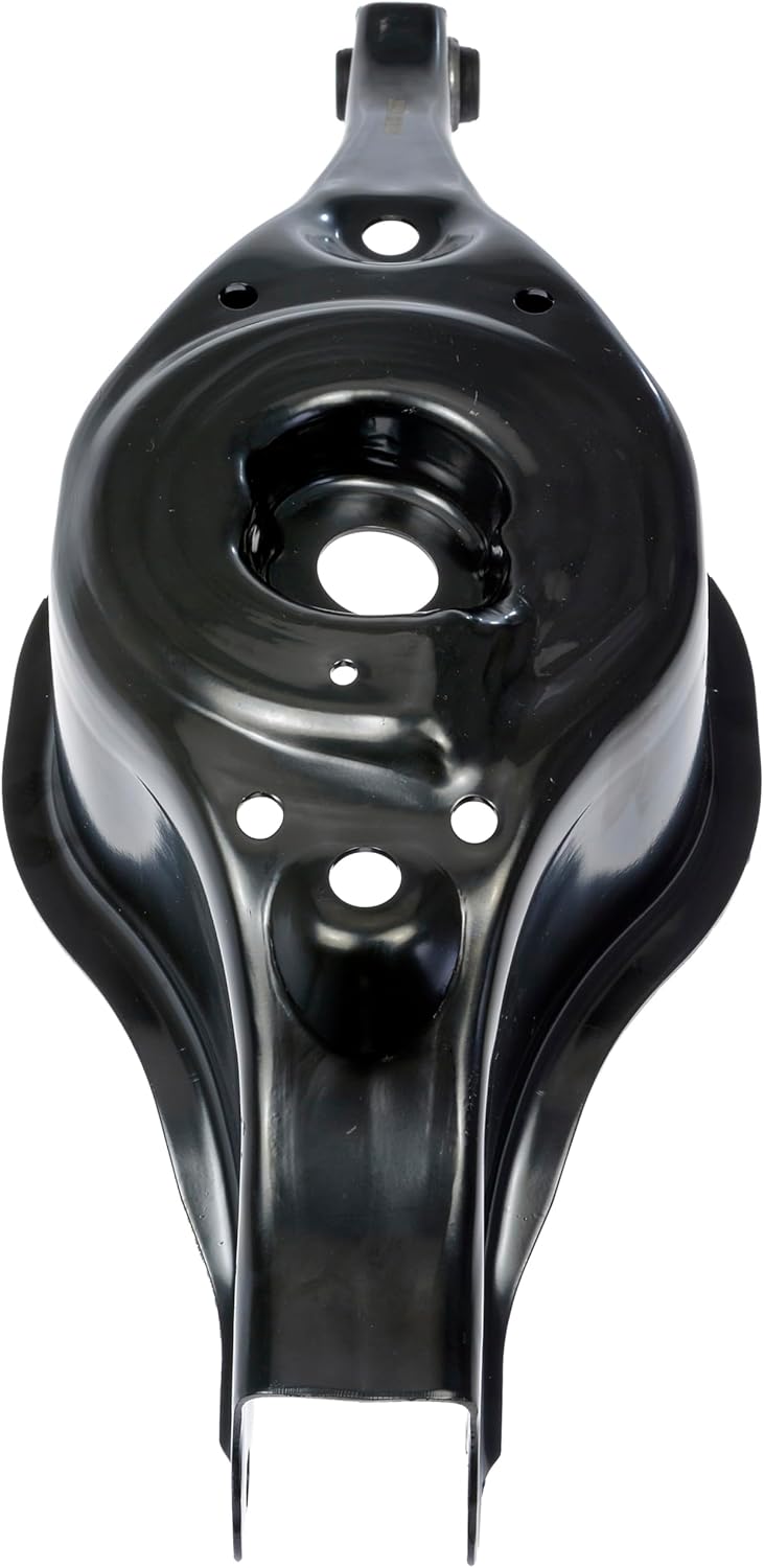
Image 7.1: Top view of the Dorman 528-101 control arm, showing mounting points and overall shape.

Image 7.2: Bottom view of the Dorman 528-101 control arm, illustrating its structural design and underside features.

Image 7.3: Side view of the Dorman 528-101 control arm, highlighting its profile and bushing location.
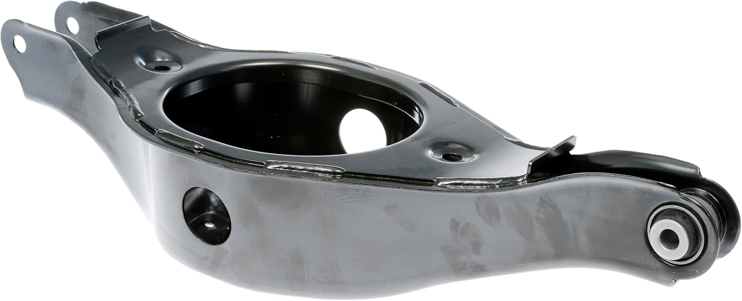
Image 7.4: Angled view of the Dorman 528-101 control arm, showing its overall form and finish.
8. Warranty and Support
Dorman products are designed for quality and reliability. For specific warranty information regarding the Dorman 528-101 Rear Lower Suspension Control Arm, please refer to the warranty documentation included with your purchase or visit the official Dorman website.
For technical support, installation assistance, or any product-related inquiries, please contact Dorman customer service. Dorman offers ASE Blue Seal certified technical support.
- Dorman Website: www.dormanproducts.com
- Technical Support: Refer to the Dorman website for contact information.
Image 8.1: Dorman commitment to support, including installation training and technical assistance.


