
Introduction
This manual provides detailed instructions for the setup, operation, and maintenance of your DIYmalls ESP32-2432S028R 2.8-inch Resistive Touch Screen Module. Please read this guide thoroughly before using the product to ensure proper functionality and longevity.
Product Overview
The DIYmalls ESP32-2432S028R is a specialized module combining an ESP32 microcontroller with a 2.8-inch resistive touch screen. It features a 320x240 pixel TFT LCD with an ILI9341 driver chip, offering 65K RGB color display. The module is designed for various embedded projects and supports code uploading via IDE or ESP32 flash tools.
Key Features:
- Integrated ESP32 module and 2.8-inch resistive touch screen.
- 320x240 pixel resolution TFT LCD with ILI9341 driver.
- 65K RGB color display.
- Supports code upload via IDE or ESP32 flash tools.
- Equipped with a TF Card Slot, RGB LED, Micro USB, Type-C, TX/RX, Speaker, BOOT, RST, and Extended IO pins.
Package Contents:
- 2 x ESP32-2432S028R Display Modules
- 2 x Dupont Female to 1.25mm 4-pin Cables
- 2 x 1m USB 2.0 to Micro USB Data Cables
- 2 x Transparent Acrylic Cases
- 2 x Touch Stylus

Image: The DIYmalls ESP32-2432S028R module, showing the front display and the rear circuit board with its transparent acrylic case.
Specifications
| Feature | Specification |
|---|---|
| Model | ESP32-2432S028R |
| Display Size | 2.8 inches (7.1 cm) |
| Display Type | TFT LCD |
| Touch Type | Resistive Touch |
| Driver Chip | ILI9341 |
| Resolution | 320 x 240 pixels |
| Display Color | 65K RGB |
| Effective Display Area | 43.2 x 57.6 mm |
| Module Dimensions | 50.0 x 86.0 mm |
| Viewing Angle | 60° |
| Operating Voltage | 5V |
| Power Consumption | Approx. 115 mA |
| Connectivity Technology | DisplayPort (Note: This refers to a generic Amazon category tag; actual connectivity is via ESP32 pins and USB) |
| Compatible Devices | Desktop (referring to development environment) |
| Operating System | Linux (referring to development environment compatibility) |
| Manufacturer Model Number | DM5815CX2 |
Setup Instructions
Follow these steps to set up your ESP32-2432S028R module:
- Unpack Components: Carefully remove all items from the packaging. Verify that all components listed in the "Package Contents" section are present.
- Assemble Acrylic Case (Optional): If not pre-assembled, attach the transparent acrylic case to protect the module. Ensure proper alignment of the display and ports.
- Identify Module Ports and Pins: Familiarize yourself with the various ports and pins on the module. Refer to the image below for a detailed layout.
- Power Connection: Connect the module to a stable 5V power source using the provided USB 2.0 to Micro USB data cable. Important: Always use a dedicated 5V charger for power. Powering directly from a PC's USB port, even if rated 5V, may not provide sufficient current for stable operation.
- Connect External Peripherals (Optional): If using external sensors or modules (e.g., BME280), connect them to the Extended IO pins using the Dupont cables. For example, to establish I2C communication with a BME280, use GPIO 22 and GPIO 27 to connect to CN1.
- Software Setup:
- Install the Arduino IDE or ESP32 flash tool on your computer.
- Install the necessary ESP32 board definitions and libraries for your development environment.
- Connect the module to your computer via the Micro USB or Type-C port for code uploading.
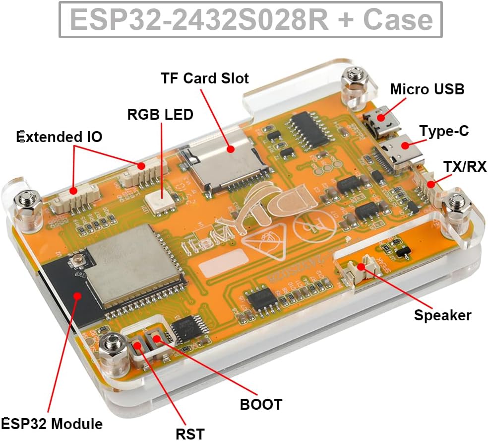
Image: Detailed view of the ESP32-2432S028R module's rear, highlighting components such as the TF Card Slot, RGB LED, Micro USB, Type-C, TX/RX pins, Speaker connector, BOOT button, RST button, ESP32 Module, and Extended IO pins.

Image: The ESP32-2432S028R module connected via 1.25mm 4-pin wires to an external sensor, demonstrating how to access GPIOs for peripheral integration.
Operating Instructions
Once the module is set up and powered, you can begin programming and interacting with it.
- Code Upload: Write your ESP32 code in your chosen IDE (e.g., Arduino IDE). Select the correct board and port, then upload the code to the module. The module supports code upload via IDE or ESP32 flash tools.
- Display Interaction: The 2.8-inch TFT LCD will display information as programmed.
- Resistive Touch Functionality: Use the provided touch stylus or a fingernail to interact with the resistive touch screen. Resistive touch screens respond to pressure, allowing for precise input.
- TF Card Usage: Insert a TF card into the TF Card Slot for data storage or loading assets (e.g., images, fonts) for your projects. Ensure the card is formatted correctly for use with ESP32.
- Speaker Output: If your project involves audio, connect a small speaker to the designated speaker connector on the module.

Image: A hand using a stylus to interact with the resistive touch screen of the ESP32-2432S028R module, demonstrating its touch input capability.
Maintenance
Proper maintenance ensures the longevity and optimal performance of your module.
- Cleaning: Gently wipe the screen and module surfaces with a soft, dry, lint-free cloth. Avoid using abrasive cleaners or solvents.
- Storage: Store the module in a cool, dry place away from direct sunlight and extreme temperatures.
- Handling: Handle the module by its edges to avoid touching the electronic components directly. Static electricity can damage sensitive components.
- Power Supply: Always ensure a stable 5V power supply. Fluctuations or incorrect voltage can damage the module.
Troubleshooting
If you encounter issues with your ESP32-2432S028R module, refer to the following common problems and solutions:
- Module does not power on or display anything:
- Verify the 5V power supply. Ensure you are using a dedicated 5V charger, not a PC USB port, as some PC ports may not provide sufficient current.
- Check all cable connections for secure fit.
- Code upload fails:
- Ensure the correct ESP32 board is selected in your IDE.
- Verify the correct COM port is selected.
- Check USB cable connection.
- Press and hold the BOOT button while uploading if necessary, then release after upload starts.
- Display shows incorrect colors or artifacts:
- Ensure the display driver (ILI9341) is correctly initialized in your code.
- Check for any loose connections to the display.
- Touch screen is unresponsive:
- Ensure the touch screen controller is correctly initialized and calibrated in your code.
- Verify physical connection of the touch screen ribbon cable.
- Debugging with RGB LED: The module includes an RGB LED on the back, which can be useful for debugging. Its pinout is as follows:
RGB LED Component GPIO Pin Red LED GPIO 4 Green LED GPIO 16 Blue LED GPIO 17 
Image: The rear of the ESP32-2432S028R module showing the illuminated RGB LED, useful for visual debugging feedback.
Support
For further assistance or inquiries, please contact DIYmalls support. You can typically find support options by visiting the DIYmalls store page on the retailer's website and looking for a "Contact Seller" or "Ask a Question" link.