
1. Introduction
This manual provides essential information for the safe and efficient installation, operation, and maintenance of the ABB ACS550-01-059A-4 Variable Frequency Drive (VFD). The ACS550-01 series is designed for a wide range of industrial applications, offering precise motor control and energy efficiency. Please read this manual thoroughly before attempting any installation or operation.
2. Safety Information
WARNING: Electrical Hazard. Risk of electric shock or arc flash. Disconnect and lock out all power sources before servicing.
- Only qualified personnel should install, operate, and maintain this equipment.
- Ensure proper grounding according to local and national electrical codes.
- Do not touch electrical connections or components when power is applied.
- Always verify that the capacitors are discharged before touching any components.
- Protect the drive from moisture, dust, and corrosive environments.
3. Product Overview
The ABB ACS550-01-059A-4 is a 30KW Variable Frequency Drive designed for controlling the speed and torque of AC induction motors. It features an integrated control panel (ACS-CP-C) for easy configuration and monitoring.

Figure 3.1: Front view of the ABB ACS550-01-059A-4 Variable Frequency Drive. This image shows the main unit with the ABB logo and control panel interface.
Key features include:
- Integrated control panel for user-friendly interface.
- Advanced motor control algorithms.
- Robust design for industrial environments.
- Energy-saving capabilities.

Figure 3.2: Two ABB VFD units, similar to the ACS550 series, displayed side-by-side to illustrate typical form factors. The unit on the right is larger, indicating higher power ratings.
4. Setup and Installation
4.1 Unpacking and Inspection
Upon receiving the drive, carefully inspect the packaging for any signs of damage. Open the package and verify that all components are present and undamaged. Report any discrepancies to your supplier immediately.
4.2 Mounting
Mount the VFD vertically on a flat, non-combustible surface. Ensure adequate clearance for cooling air circulation around the unit. Refer to the dimension diagram for proper spacing requirements.
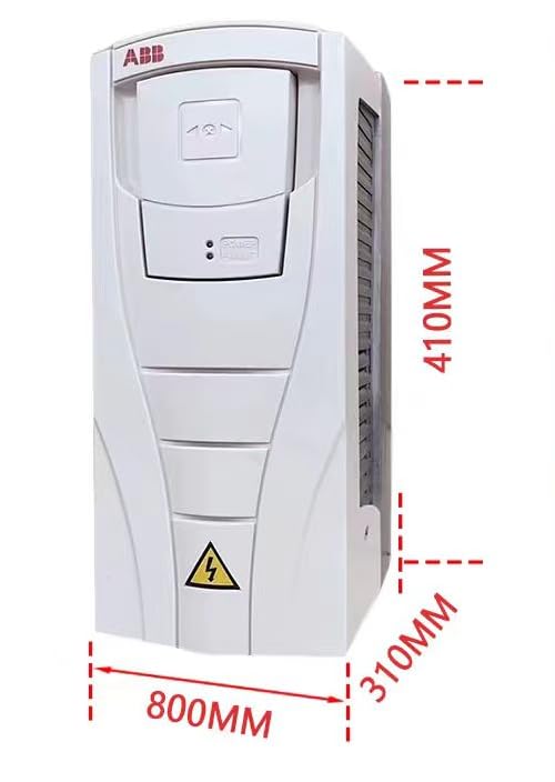
Figure 4.1: Dimensional drawing of an ABB VFD unit, providing measurements for height (410mm), width (310mm), and depth (800mm). These dimensions are crucial for proper installation planning.
4.3 Wiring
All wiring must comply with local and national electrical codes. Connect the main power supply, motor, and control signals to the appropriate terminals. Use shielded cables for control wiring to minimize electromagnetic interference.
- Power Wiring: Connect the incoming AC power to the L1, L2, L3 terminals. Connect the motor to the U, V, W terminals.
- Grounding: Ensure a proper ground connection to the protective earth (PE) terminal.
- Control Wiring: Connect digital inputs, analog inputs, and relay outputs as required by your application.
4.4 Initial Power-Up
Before applying power, double-check all wiring connections. Once verified, apply power to the drive. The control panel should illuminate, indicating successful power-up. Follow the initial setup wizard on the control panel to configure basic parameters.
5. Operating Instructions
5.1 Control Panel (ACS-CP-C)
The ACS-CP-C control panel allows for local control, parameter setting, and monitoring of the drive. It features a display, navigation buttons, and a start/stop button.
- NAVIGATOR Key: Used for navigating through menus and parameters.
- ENTER Key: Confirms selections and enters values.
- START/STOP Buttons: Initiates and halts motor operation.
- LOCAL/REMOTE Key: Toggles between local control (via panel) and remote control (via I/O or fieldbus).
5.2 Basic Operation
- Ensure the drive is in LOCAL mode if operating from the control panel.
- Press the START button to begin motor operation.
- Adjust the motor speed using the appropriate parameter or analog input.
- Press the STOP button to halt motor operation.
5.3 Parameter Setting
The drive's behavior can be customized by adjusting various parameters. Refer to the detailed programming manual for a complete list of parameters and their functions. Common parameters include motor nominal voltage, current, frequency, and acceleration/deceleration times.
6. Maintenance
Regular maintenance ensures the longevity and reliable operation of your VFD. Always disconnect power before performing any maintenance.
- Cleaning: Periodically clean the cooling fins and fans to ensure proper airflow. Use compressed air to remove dust and debris.
- Connections: Check all electrical connections for tightness and signs of corrosion.
- Environmental Conditions: Ensure the operating environment remains within specified temperature and humidity limits.
- Capacitor Check: For long-term storage or after extended periods of inactivity, follow manufacturer guidelines for capacitor re-forming.
7. Troubleshooting
This section provides solutions to common issues. For more complex problems, consult the detailed troubleshooting guide or contact technical support.
| Problem | Possible Cause | Solution |
|---|---|---|
| Drive does not power on | No input power; Blown fuse; Incorrect wiring | Check power supply; Replace fuse; Verify wiring connections. |
| Motor does not start | Drive in REMOTE mode; Fault condition; Incorrect parameters | Switch to LOCAL mode; Check fault codes on panel; Verify motor parameters. |
| Overcurrent fault | Motor overload; Short circuit; Rapid acceleration | Reduce load; Check motor wiring; Increase acceleration time. |
| Overvoltage fault | High input voltage; Rapid deceleration; Regenerative load | Check input voltage; Increase deceleration time; Consider braking resistor. |
8. Specifications
| Parameter | Value |
|---|---|
| Model | ACS550-01-059A-4 |
| Power Rating | 30 KW |
| Manufacturer | Dalastwoo (as listed by seller) |
| ASIN | B0F9VJK173 |
| Date First Available | December 5, 2022 |
9. What's in the Box
The standard package for the ABB ACS550-01-059A-4 Variable Frequency Drive typically includes:
- ABB ACS550-01-059A-4 VFD Unit
- ACS-CP-C English Control Panel
- Basic documentation (e.g., Quick Start Guide)
Note: Contents may vary slightly based on specific supplier packaging.
10. Warranty and Support
For warranty information, please refer to the documentation provided with your purchase or contact the seller directly. Technical support can typically be obtained from the authorized ABB distributor or the point of purchase. When contacting support, please have your product model number (ACS550-01-059A-4) and serial number ready.
For additional resources and detailed manuals, visit the official ABB website or contact their customer service.


