1. Safety Precautions
Before installing or operating the ETURBEV ES100 VFD Inverter, please read and understand this instruction manual thoroughly. Failure to follow safety guidelines may result in personal injury or equipment damage.
- Ensure power is disconnected before any installation, wiring, or maintenance.
- Only qualified personnel should perform installation and wiring.
- Verify correct voltage and current ratings for your specific model and application.
- Do not touch internal components immediately after power-off, as residual voltage may be present.
- Install the inverter in a clean, dry, and well-ventilated environment, away from direct sunlight, corrosive gases, and excessive vibration.
- Proper grounding is essential for safe operation.
2. Product Overview
The ETURBEV ES100 Variable Frequency Drive (VFD) is designed to control the speed of AC motors. It offers robust performance and protective functions for various industrial applications. This series supports both single-phase 220V and three-phase 380V input configurations, providing a versatile solution for motor speed control.

Figure 2.1: Front view of the ETURBEV ES100 VFD Inverter, showing the control panel and display.
Key Features:
- Control Modes: V/F control, Sensorless Vector Control (Open Loop Vector Control) for asynchronous and synchronous motors.
- Input Voltage Options:
- ES100G1VFD: 1-phase 220V (50/60Hz), 3-phase 220V (50/60Hz), DC 200-400V
- ES100G2VFD: 3-phase 220V (50/60Hz), DC 200-400V
- ES100G3VFD: 3-phase 380-480V (50/60Hz), DC 380-700V
- Output Voltage: 3-phase, 0-240V (for 220V input models), 3-phase, 0-480V (for 380V input models).
- Protective Functions: Overcurrent, overvoltage, undervoltage, module fault, electric thermal relay, overheat, short circuit, input/output phase loss, motor parameter abnormality, internal memory fault.
- Built-in PID Control: For applications requiring constant pressure or flow.
- Built-in RS485: For communication and remote control.
- Built-in 24V Power Supply.
- Built-in Braking Unit: For quick start and stop applications (0.75-7.5KW models).
3. Setup and Installation
3.1 Mounting
Mount the VFD vertically on a stable, non-flammable surface. Ensure adequate clearance around the unit for proper ventilation and heat dissipation. Avoid mounting in areas with excessive dust, moisture, or corrosive substances.

Figure 3.1: Internal view of the ETURBEV ES100 VFD, showing the cooling fan and heat sink, emphasizing the need for proper ventilation.
3.2 Wiring
All wiring must comply with local electrical codes and regulations. Use appropriate wire gauges for power connections. Ensure all connections are secure to prevent loose contacts and potential hazards.
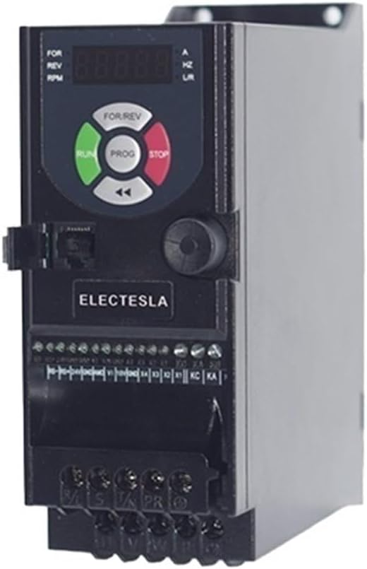
Figure 3.2: Side view of the ETURBEV ES100 VFD, illustrating the terminal blocks for power input, motor output, and control signals.
Power Input Terminals:
- Connect the main power supply to the designated input terminals (e.g., R, S, T for 3-phase; L, N for 1-phase).
- Ensure the input voltage matches the VFD's rating (e.g., 1-phase 220V, 3-phase 220V, or 3-phase 380V).
Motor Output Terminals:
- Connect the motor leads to the U, V, W output terminals.
- Ensure the motor's rated voltage and current are compatible with the VFD's output.
Control Terminals:
- Logic Input (X1-X4): Used for functions like positive/negative rotation, jog, multi-segment speed, and terminal UP/DOWN frequency.
- Pulse Input (X3): Supports 0-100KHz input range.
- Analog Input (VI): 0-10V or 0-20mA (selectable via DIP switch) for frequency reference.
- Analog Output (AMO): 0-10V for indicating running frequency, output current, etc.
- Relay Output (KA/KB/KC): One normally open, one normally closed contact for status indication or external control.
- RS485: For serial communication with external devices.
Refer to the detailed wiring diagram in the full product manual for specific terminal assignments and connection procedures.
4. Operating Instructions
The ES100 VFD features a digital keypad for easy operation and parameter setting.

Figure 4.1: Detailed view of the ES100 VFD operation panel, highlighting the function of each button and indicator.
4.1 Control Panel Functions:
- FOR/REV Select Button: Toggles motor rotation direction (Forward/Reverse).
- RUN Button: Initiates motor operation.
- PROG (Menu) Button: Enters/exits parameter setting mode, navigates menus.
- STOP Button: Halts motor operation.
- Shift Key (<): Used for shifting digits during parameter entry.
- Encoder (Rotary Knob): Adjusts frequency, navigates parameters, and changes values.
- Status Indicator: Displays operational status, frequency, current, voltage, etc. (e.g., FOR, REV, RPM, A, HZ, U/R).
4.2 Basic Operation:
- Power On: Ensure all wiring is correct and secure, then apply power to the VFD.
- Set Frequency: Use the Encoder knob to adjust the desired output frequency. The display will show the set frequency.
- Select Direction: Press the FOR/REV button to choose forward or reverse rotation if needed.
- Start Motor: Press the RUN button. The motor will accelerate to the set frequency.
- Stop Motor: Press the STOP button. The motor will decelerate and stop.
4.3 Parameter Setting:
To access and modify parameters, press the PROG button. Use the Encoder to navigate through parameter groups and individual parameters. Press PROG again to select a parameter, use the Encoder to change its value, and press PROG to save. Use the Shift Key to move between digits when entering numerical values.
Refer to the detailed parameter list in the full product manual for specific parameter definitions and ranges.
5. Maintenance
Regular maintenance ensures the longevity and reliable operation of your ETURBEV ES100 VFD.
- Cleaning: Periodically clean the VFD's exterior and ventilation openings to prevent dust accumulation, which can hinder cooling. Use a soft, dry cloth. Do not use liquid cleaners.
- Fan Inspection: Check the cooling fan for proper operation and cleanliness. Replace if noisy or not functioning correctly.
- Terminal Connections: Periodically inspect all wiring terminals for tightness. Loose connections can cause overheating or intermittent operation.
- Environmental Conditions: Ensure the operating environment remains within specified temperature and humidity ranges.
- Capacitor Life: Electrolytic capacitors have a finite lifespan. If the VFD is used continuously for many years, consider professional inspection or replacement of capacitors.
Always disconnect power before performing any maintenance tasks.
6. Troubleshooting
This section provides solutions to common issues you might encounter with the ES100 VFD. For more complex problems, contact technical support.
| Problem | Possible Cause | Solution |
|---|---|---|
| VFD does not power on | No input power; Incorrect wiring; Blown fuse | Check power supply; Verify wiring connections; Inspect and replace fuses if necessary. |
| Motor does not run | STOP button pressed; Incorrect frequency setting; Motor wiring error; Overload protection triggered | Press RUN; Adjust frequency; Check motor connections (U, V, W); Check for overload condition and reset. |
| Overcurrent fault (OC) | Motor overload; Short circuit in motor wiring; Rapid acceleration/deceleration; Incorrect motor parameters | Reduce motor load; Check motor wiring for shorts; Increase acceleration/deceleration time; Verify motor parameters. |
| Overvoltage fault (OV) | Input voltage too high; Rapid deceleration with high inertia load; Regenerative braking issue | Check input voltage; Increase deceleration time; Consider adding an external braking resistor if applicable. |
| Undervoltage fault (UV) | Input voltage too low; Power supply instability | Check input voltage stability; Ensure power supply meets VFD requirements. |
Always refer to the VFD's display for specific error codes and consult the full manual for detailed troubleshooting steps.
7. Specifications
| Feature | Description |
|---|---|
| Model Series | ES100 VFD Inverter |
| Input Voltage (ES100G1VFD) | 1-phase 220V (50/60Hz), 3-phase 220V (50/60Hz), DC 200-400V |
| Input Voltage (ES100G2VFD) | 3-phase 220V (50/60Hz), DC 200-400V |
| Input Voltage (ES100G3VFD) | 3-phase 380-480V (50/60Hz), DC 380-700V |
| Output Voltage | 3-phase, 0-240V (for 220V input); 3-phase, 0-480V (for 380V input) |
| Power Range | 0.4KW - 4KW (Specific models vary) |
| Control Mode | V/F Control, Sensorless Vector Control (Open Loop Vector Control) |
| Logic Input | 4 digital inputs (X1-X4) for various control functions |
| Pulse Input | X3 terminal, 0-100KHz range |
| Analog Input | VI: 0-10V / 0-20mA (selectable) |
| Analog Output | AMO: 0-10V |
| Relay Output | KA/KB/KC (1 NO, 1 NC) |
| Communication | Built-in RS485 |
| Built-in Braking Unit | Yes (for 0.75-7.5KW models) |
| Product Dimensions | 0.39 x 0.39 x 0.39 inches |
| Item Weight | 1.76 ounces |
Note: Dimensions and weight provided are general. Specific values may vary based on the power rating of the VFD model.
8. Warranty and Support
Information regarding product warranty and technical support is typically provided with the purchase documentation or on the manufacturer's official website. Please refer to these resources for details on warranty coverage, service procedures, and contact information for technical assistance.
For any issues not covered in this manual, or for advanced technical inquiries, it is recommended to contact ETURBEV customer support or a certified service technician.


