
1. Introduction
Thank you for choosing the GODIYMODULES 3S 12V 18650 10A Li-ion Battery Protection Board (BMS). This module is designed to provide essential protection for 3-series (3S) 18650 lithium-ion battery packs, ensuring their safety and extending their lifespan. It safeguards against common issues such as overcharge, over-discharge, over-current, and short circuits. Please read this manual carefully before installation and use to ensure proper operation and safety.
2. Product Overview
The 3S 12V 10A BMS is a compact and efficient battery management system suitable for various applications using 3.7V lithium cells, resulting in a nominal 10.8V, 11.1V, or 12.6V battery pack. Its primary function is to monitor the voltage of each cell and the overall current flow, disconnecting the load or charger when unsafe conditions are detected. This ensures the longevity and safe operation of your battery pack.
Key Features:
- Overcharge Protection: Prevents individual cells from being charged beyond their safe voltage limit (4.25-4.35V±0.05V).
- Over-discharge Protection: Prevents individual cells from being discharged below their safe voltage limit (2.3-3.0V±0.05V).
- Over-current Protection: Limits the discharge current to prevent damage to the battery and the BMS (Maximum discharge current: 10A, Transient current: 9A-10A).
- Short Circuit Protection: Automatically disconnects the battery in case of a short circuit.
- Compact Design: Small form factor (approx. 50x16x1mm) for easy integration into battery packs.

Figure 1: Top view of the 3S 12V 10A BMS module, showing components and connection points.

Figure 2: Bottom view of the 3S 12V 10A BMS module, showing solder pads and markings.
3. Specifications
| Feature | Specification |
|---|---|
| Model | 3S 12V 10A Li-ion Battery Protection Board |
| Battery Type | 3-series (3S) 3.7V Li-ion 18650 batteries |
| Nominal Voltage | 10.8V / 11.1V / 12.6V (depending on cell voltage) |
| Maximum Discharge Current | 10A |
| Maximum Working Current | 5A-8A |
| Transient Current | 9A-10A |
| Overcharge Detection Voltage | 4.25-4.35V ± 0.05V per cell |
| Over-discharge Detection Voltage | 2.3-3.0V ± 0.05V per cell |
| Short Circuit Protection | Yes |
| Dimensions | Approx. 50mm x 16mm x 1mm |
| Compatible Devices | Devices using 3.7V lithium cores (10.8V, 11.1V, 12.6V batteries) |
4. Safety Instructions
- Always handle lithium-ion batteries with care.
- Ensure correct polarity when connecting batteries to the BMS. Incorrect wiring can cause damage to the BMS, batteries, or lead to fire.
- Do not exceed the specified maximum discharge current (10A).
- Use appropriate charging equipment designed for lithium-ion batteries.
- Avoid short-circuiting the battery pack or the BMS output.
- Keep the BMS module away from moisture, extreme temperatures, and static electricity.
- If you are unsure about any wiring steps, consult a qualified professional.
- This BMS is designed for 3-series (3S) battery packs only. Do not use with other configurations.
5. Setup and Wiring
Proper wiring is critical for the safe and effective operation of the BMS. Refer to the wiring diagram below and follow the steps carefully.
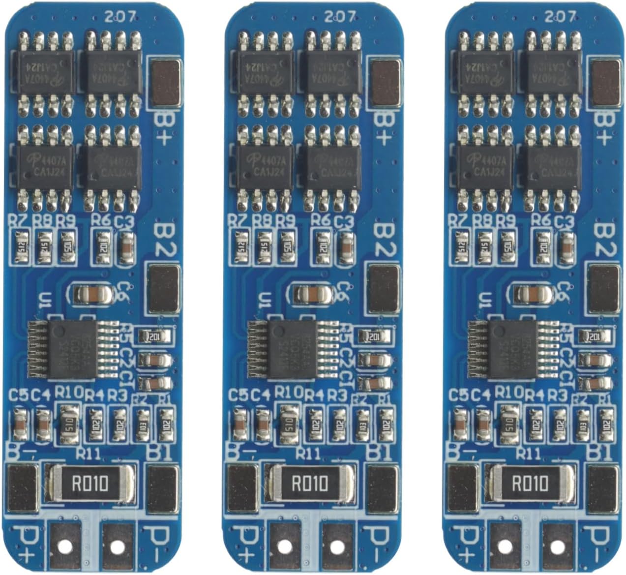
Figure 3: Wiring diagram for connecting three 18650 cells to the 3S 12V 10A BMS module.
Wiring Steps:
- Connect B- (Battery Negative): Connect the negative terminal of the first battery cell (Cell 1) to the B- pad on the BMS. This is the main negative terminal for the entire battery pack.
- Connect B1 (Cell 1 Positive / Cell 2 Negative): Connect the positive terminal of Cell 1 to the negative terminal of the second battery cell (Cell 2). Then, connect this junction point to the B1 pad on the BMS.
- Connect B2 (Cell 2 Positive / Cell 3 Negative): Connect the positive terminal of Cell 2 to the negative terminal of the third battery cell (Cell 3). Then, connect this junction point to the B2 pad on the BMS.
- Connect B+ (Battery Positive): Connect the positive terminal of the third battery cell (Cell 3) to the B+ pad on the BMS. This is the main positive terminal for the entire battery pack.
- Connect P- (Output/Charge Negative): This pad is the negative terminal for both charging and discharging. Connect your load's negative terminal or charger's negative terminal here.
- Connect P+ (Output/Charge Positive): This pad is the positive terminal for both charging and discharging. Connect your load's positive terminal or charger's positive terminal here. Note that P+ is typically connected directly to B+ on the BMS board itself, as shown in the diagram.
Important: Always connect the balance wires (B-, B1, B2, B+) to the BMS before connecting the main charge/discharge wires (P-, P+). Ensure all connections are secure and properly insulated to prevent short circuits.
6. Operation
Once correctly wired, the BMS operates automatically to protect your battery pack. It continuously monitors cell voltages and current flow.
- Charging: When charging, the BMS will prevent any individual cell from exceeding its overcharge detection voltage. If a cell reaches this limit, the BMS will stop the charging process for the entire pack.
- Discharging: During discharge, the BMS will prevent any individual cell from dropping below its over-discharge detection voltage. If a cell reaches this limit, the BMS will cut off the discharge to protect the battery. It will also cut off discharge if the total current exceeds the maximum discharge current or if a short circuit is detected.
- Recovery: After a protection event (e.g., over-discharge), the BMS typically recovers automatically once the condition is resolved (e.g., by applying a charge to an over-discharged pack). For over-current or short-circuit protection, removing the fault condition usually allows for automatic recovery.
7. Maintenance
The 3S 12V 10A BMS module requires minimal maintenance. However, following these guidelines can help ensure its long-term reliability:
- Regular Inspection: Periodically inspect all wiring connections for looseness or corrosion.
- Cleanliness: Keep the module clean and free from dust and debris. Use a soft, dry cloth for cleaning.
- Environmental Conditions: Ensure the module operates within its specified temperature range and avoid exposure to excessive humidity.
- Battery Health: Monitor the overall health of your battery cells. A BMS cannot compensate for severely damaged or unbalanced cells.
8. Troubleshooting
If you encounter issues with your BMS, consider the following troubleshooting steps:
- No Output Voltage (P+ / P-):
- Check all wiring connections for correctness and secure contact.
- Verify that the battery pack voltage is within the operational range (above over-discharge voltage).
- Ensure no short circuit is present on the output terminals.
- If the pack was over-discharged, try connecting a charger to reactivate the BMS.
- Battery Not Charging:
- Confirm the charger is functioning correctly and is suitable for 3S Li-ion batteries.
- Check if any individual cell voltage has reached the overcharge protection threshold.
- Inspect charger connections to P+ and P-.
- BMS Cuts Off Prematurely (e.g., at 12.8V):
- This can occur if the charger voltage is too low or if the cells are not perfectly balanced. Ensure your charger provides a voltage higher than the desired full charge voltage (e.g., 13.5V for a 12.6V pack).
- Individual cell voltages might be reaching their overcharge limit before the total pack voltage reaches 12.6V. Consider balancing your cells before connecting to the BMS, or use a charger with a lower current to allow for better balancing by the BMS (if it has passive balancing, which this basic model might not).
- Overheating:
- Reduce the load current if the BMS is consistently running hot.
- Ensure adequate ventilation around the module.
If problems persist, re-verify all wiring against the diagram and consult the manufacturer's support.
9. Warranty and Support
This GODIYMODULES 3S 12V 10A BMS module comes with a 2-year manufacturer's warranty from the date of purchase. This warranty covers defects in materials and workmanship under normal use.
The warranty does not cover damage caused by:
- Improper installation or wiring.
- Misuse, abuse, or negligence.
- Unauthorized modifications or repairs.
- Operating outside the specified environmental conditions.
- Overloading beyond the maximum current ratings.
For warranty claims or technical support, please contact GODIYMODULES customer service through the platform where the product was purchased, providing your order details and a description of the issue.