
1. Introduction
This manual provides essential information for the safe and effective operation of your haxiaoer 55A Plasma Cutter and 145A MIG Welder Machine. This versatile unit combines a 55A plasma cutter with a 145A multi-process welder, supporting Flux Core MIG, Stick, and Lift TIG welding. It features dual voltage input (110V/220V) and a non-touch pilot arc for plasma cutting. Please retain this manual for future reference.

Figure 1.1: haxiaoer 55A Plasma Cutter and 145A MIG Welder Machine. This image displays both the plasma cutter and MIG welder units along with their respective accessories, including torches, ground clamps, and welding wire.
2. Safety Information
Always prioritize safety when operating welding and cutting equipment. Failure to follow safety guidelines can result in serious injury or death.
2.1 General Safety Precautions
- Eye and Face Protection: Always wear a welding helmet with appropriate shade lenses to protect against arc flash and sparks.
- Body Protection: Wear flame-resistant clothing, heavy-duty gloves, and safety shoes.
- Ventilation: Ensure adequate ventilation to remove welding fumes and gases from the work area.
- Fire Prevention: Keep a fire extinguisher nearby. Remove flammable materials from the work area.
- Electrical Safety: Ensure proper grounding. Do not operate in wet conditions. Inspect cables for damage before use.
- Compressed Air (Plasma Cutter): Ensure the air compressor is properly maintained and provides clean, dry air at the recommended pressure.
3. Product Overview
The haxiaoer 55A Plasma Cutter and 145A MIG Welder is a robust, multi-functional unit designed for various metalworking tasks. It features advanced inverter technology for stable output and efficiency.
3.1 Key Features
- Non-Touch Pilot Arc Plasma Cutting: Allows cutting through painted, rusted, or dirty surfaces without direct contact, extending consumable life.
- Multi-Process Welding: Supports Flux Core Gasless MIG, Stick (MMA), and Lift TIG welding (TIG torch sold separately).
- Dual Voltage Input: Automatically detects and adapts to 110V or 220V power sources.
- Large LED Display: Provides clear, real-time display of cutting and welding parameters.
- Synergy Control (MIG): Simplifies setup by automatically matching wire feed speed and voltage to the selected current and wire size.
- Multiple Protection Functions: Includes overheat, overcurrent, and overload protection for enhanced safety and machine longevity.

Figure 3.1: Pilot Arc Plasma Cutter in operation. This image shows the plasma cutter unit with its torch actively cutting metal, highlighting the non-touch pilot arc feature.
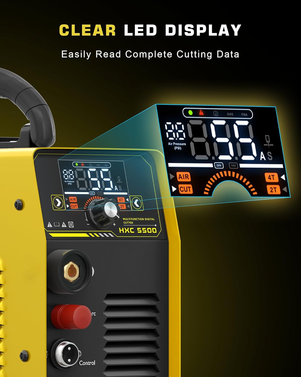
Figure 3.2: Clear LED Display of the Plasma Cutter. A close-up view of the plasma cutter's control panel, showing the digital LED display with various settings and indicators for air pressure and current.

Figure 3.3: MIG Welder Button Introduction. This image illustrates the control panel of the MIG welder, labeling key components such as the screen display, welding mode selector, automatic plate thickness setting, welding wire settings, MMA settings, and current knob.
4. Setup
Proper setup is crucial for safe and effective operation. Ensure the machine is placed on a stable, level surface in a well-ventilated area.
4.1 Power Connection
- Verify your power supply matches the machine's dual voltage capability (110V/220V). The machine automatically detects the input voltage.
- Connect the power cord to a suitable grounded outlet.
4.2 Plasma Cutter Setup
- Connect the plasma torch to the designated port on the front panel.
- Attach the ground clamp to the workpiece, ensuring good electrical contact.
- Connect an air compressor to the air inlet on the rear of the machine. Ensure the air supply is clean, dry, and regulated to the recommended pressure (refer to specifications).
4.3 MIG Welder Setup (Flux Core Gasless)
- Open the wire feed compartment.
- Install the flux core welding wire spool onto the spindle, ensuring it rotates freely.
- Thread the welding wire through the guide tube and into the drive rollers. Adjust the drive roller tension to prevent slipping or crushing the wire.
- Feed the wire through the MIG torch liner until it exits the contact tip.
- Connect the MIG torch to the appropriate port.
- Attach the ground clamp to the workpiece, ensuring good electrical contact.

Figure 4.1: Welding Wire Feeding Operation. This diagram illustrates the process of installing and feeding welding wire into the MIG welder, showing the spool, drive rollers, and the path of the wire to the torch.

Figure 4.2: 3 in 1 Connection Method. This image displays the connection setups for Gasless Flux Core MIG, Stick, and Lift TIG welding modes, showing how the torch and ground clamp are connected for each process.
5. Operating Instructions
Familiarize yourself with the control panel and settings before beginning any operation.
5.1 Plasma Cutting Operation
- Turn on the machine and select the 'AIR CUT' mode.
- Adjust the cutting current (Amps) based on the material thickness. The LED display will show the current settings.
- Ensure proper air pressure is supplied.
- Position the plasma torch nozzle approximately 1/8 inch (3mm) above the workpiece.
- Press the torch trigger to initiate the pilot arc and begin cutting. Maintain a steady travel speed for a clean cut.
- Recommended nozzle (tip) size: 1.0mm/0.39inch for best cutting results.
- Cutting Thickness: Up to 3/4'' @220V (1/2''@110V). Ideal clean cut thickness: 1/3''@110V, 1/2''@220V.
5.2 MIG Welding Operation (Flux Core Gasless)
- Turn on the machine and select the 'MIG' mode.
- Use the synergy control feature: Select the wire size and adjust the current knob. The machine will automatically set the appropriate wire feed speed and voltage.
- Ensure the ground clamp is securely attached to the workpiece.
- Position the MIG torch at the desired starting point.
- Press the torch trigger to start welding. Maintain a consistent arc length and travel speed.

Figure 5.1: Synergy Control for MIG Welding. This image illustrates the three steps for setting up MIG welding: selecting MIG mode, selecting wire size, and adjusting the current, demonstrating the machine's synergy control feature.
5.3 Stick Welding Operation (MMA)
- Connect the electrode holder and ground clamp to the appropriate terminals.
- Select 'ARC' (MMA) mode.
- Insert the welding electrode into the holder.
- Adjust the welding current (Amps) based on the electrode type and material thickness.
- Strike an arc by lightly touching and quickly lifting the electrode from the workpiece.
- The machine features built-in adjustable arc force and hot start functions for improved arc ignition and stability.

Figure 5.2: Excellent Stick Welding Machine. This image shows a welder performing stick welding, with a close-up inset of a completed weld bead, demonstrating the quality achievable with the machine's stick welding function.
5.4 Lift TIG Welding Operation
Note: An extra TIG torch is required for Lift TIG welding and is not included with this unit. (ASIN: B0F1CHCG4W for compatible TIG torch).
- Connect the TIG torch and ground clamp to the appropriate terminals.
- Select 'TIG' mode.
- Adjust the welding current.
- Touch the tungsten electrode lightly to the workpiece to initiate the arc, then lift slightly to establish the arc.

Figure 5.3: 3 in 1 Flux Core Welder. This image visually represents the three welding processes supported: Flux MIG, ARC (Stick), and Lift TIG, showing a welder performing each type of weld.
6. Maintenance
Regular maintenance ensures the longevity and optimal performance of your machine.
- Cleaning: Periodically clean the machine's exterior with a dry cloth. Use compressed air to blow out dust from the internal components and vents.
- Cable Inspection: Regularly inspect all cables, torches, and clamps for cuts, fraying, or loose connections. Replace damaged components immediately.
- Consumables: For plasma cutting, regularly check and replace worn nozzles and electrodes. For MIG welding, inspect and replace contact tips and ensure the wire liner is clean.
- Air Filter (Plasma Cutter): Check and clean or replace the air filter on the plasma cutter's air inlet as needed to ensure a clean air supply.
7. Troubleshooting
This section provides solutions for common issues. For problems not listed, contact customer support.

Figure 7.1: Multiple Protection Functions and Error Codes. This image displays a table of error codes (E01-E06) for the plasma cutter, indicating issues like pilot arc failure, temperature drops, and air access problems, along with their corresponding solutions.
| Problem | Possible Cause | Solution |
|---|---|---|
| No Power | Power cord unplugged, circuit breaker tripped, machine switch off. | Check power connections, reset breaker, turn on machine switch. |
| No Arc (Plasma) | Insufficient air pressure, worn consumables, poor ground connection, torch trigger not pressed. | Check air supply, replace nozzle/electrode, ensure good ground, press trigger firmly. |
| No Arc (Welding) | Poor ground connection, incorrect settings, electrode/wire not making contact. | Ensure good ground, adjust current/voltage, check wire feed. |
| Wire Feed Issues (MIG) | Drive roller tension incorrect, clogged liner, wrong contact tip, tangled wire. | Adjust tension, clean liner, replace contact tip, untangle wire. |
| Overheat Protection Activated | Exceeded duty cycle, poor ventilation. | Allow machine to cool down, ensure clear airflow around vents. |
8. Specifications
Technical parameters for the haxiaoer 55A Plasma Cutter and 145A MIG Welder Machine.

Figure 8.1: Technical Parameters for MIG145. This image presents a detailed table of technical specifications for the MIG145 model, including input voltage, current ranges for MIG and ARC, duty cycle, and protection class.
| Feature | Description |
|---|---|
| Model | HXC550D (Plasma Cutter) / MIG145 (Welder) |
| Input Voltage | 110V/220V (Automatic Detection) |
| Frequency | 50/60Hz |
| Plasma Cutting Current | 55A Max |
| MIG Welding Current | 145A Max |
| Duty Cycle | 60% |
| Plasma Cutting Thickness | Up to 3/4'' @220V (1/2''@110V) |
| Protection Class | IP21S |
| Cooling | Fan Cooled |
9. Warranty and Support
haxiaoer provides reliable customer support for its products.
- Customer Service: For any questions or assistance, please contact haxiaoer customer support via Amazon email. Our professional team is available to assist you.
- Warranty: Please refer to your purchase documentation for specific warranty terms and conditions.