1. Introduction
1.1 Product Overview
The Y&H ESS Plus Series is an integrated household energy storage system designed for photovoltaic applications. This all-in-one unit combines a solar inverter, lithium-ion battery, and MPPT controller, supporting grid-connected, off-grid, and hybrid operation modes. It provides a stable and efficient energy solution for various power requirements.
1.2 Key Features
- Scalable Power Hub: Features a 4.2KW hybrid inverter with expandable lithium battery capacity (5.12kWh to 15.36kWh, configurable in 5.12kWh increments). Delivers 4200W stable AC output.
- Smart Solar Integration: Includes a 120A MPPT solar charger with a wide PV input voltage range (60-500VDC) for efficient solar energy harvesting. Supports auto-restart during AC recovery and cold-starts at -10°C.
- Advanced Safety & Control: Equipped with a Battery Management System (BMS) for protection against overcharge and over-discharge. Features a one-key factory reset and remote monitoring capabilities via iOS/Android applications.
- Industrial-Grade Durability: Designed with an IP65-rated anti-dust kit, universal wheels for mobility, and a compact form factor (441x231x701mm). The stackable design allows for multi-unit clustering.
- Dual-Functionality & Efficiency: Provides pure sine wave AC output (PF 1.0) suitable for sensitive electronics. Dual output ports allow prioritization of critical loads. Supports hybrid operation for seamless grid interaction.
2. Safety Instructions
Read all instructions and warnings carefully before installation and operation. Failure to follow these instructions may result in electric shock, fire, severe injury, or death.
- Qualified Personnel: Installation and maintenance must be performed by qualified personnel only.
- Electrical Safety: Ensure all power sources are disconnected before performing any wiring or maintenance. Use appropriate personal protective equipment (PPE).
- Battery Handling: Lithium-ion batteries can be dangerous if mishandled. Do not short-circuit, puncture, or expose to extreme temperatures.
- Ventilation: Ensure adequate ventilation around the unit to prevent overheating.
- Environment: Do not install in direct sunlight, high humidity, or near flammable materials. The unit has an IP65 rating for dust, but avoid direct water exposure.
- Grounding: The system must be properly grounded according to local electrical codes.
3. Product Components and Diagrams
3.1 System Overview
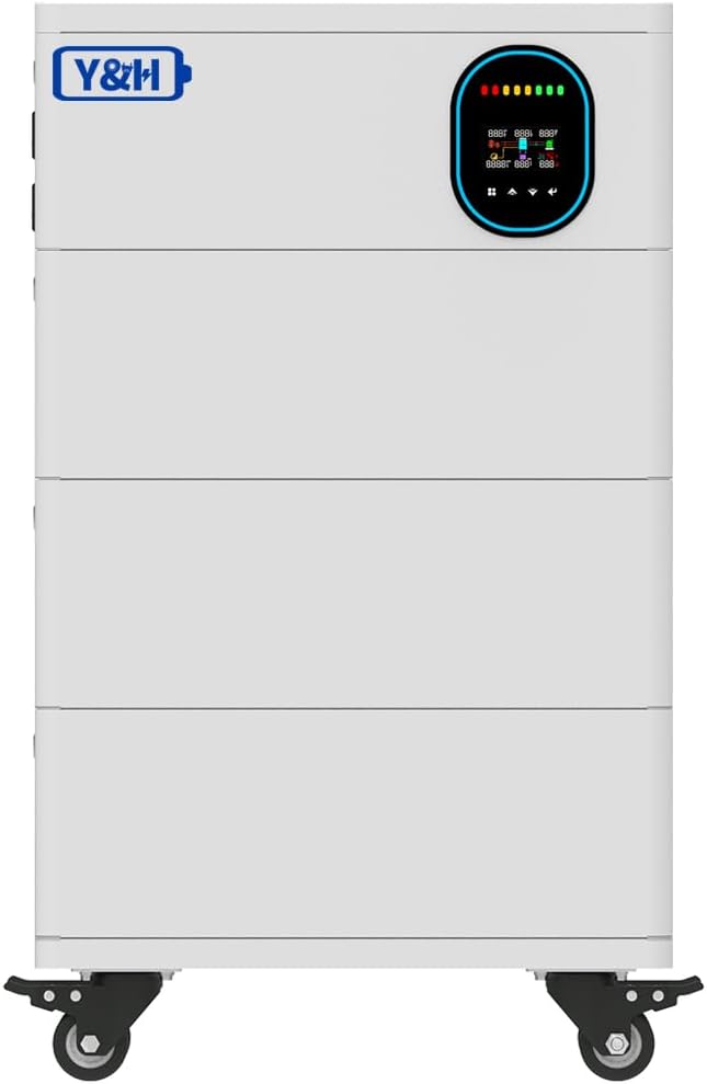
This image displays the front of the Y&H ESS Plus system, highlighting its compact and modular design. The top section features an integrated display panel for monitoring system status, while the lower sections represent the stackable battery modules. The unit is equipped with wheels for easy repositioning.
3.2 System Diagram

This diagram illustrates the operational flow of the Y&H ESS Plus system. It shows how solar modules, the utility grid, and a generator can supply power to the energy storage station. The stored energy is then distributed to home appliances. The arrows indicate the bidirectional flow of energy, demonstrating the system's versatility in managing power sources and loads.
3.3 Back Panel Connections

This image provides a comprehensive view of the back panel connections for the Y&H ESS Plus system. It labels key components such as AC input/output, PV input, battery input, RS485/BMS/WiFi ports, and various switches for inverter and battery control. The diagram also highlights the anti-dust kit and output receptacles.
3.4 Back Panel Detail - Inverter Section

This close-up image focuses on the upper section of the back panel, specifically the inverter connections. It clearly shows the AC IN switch, Battery Switch, RS485/BMS/WiFi port, RS232 port, SECOND AC OUT, MAIN AC OUT, PV IN, and AC IN terminals. This view is crucial for understanding the wiring of the inverter component.
3.5 Back Panel Detail - Battery Section

This image provides a detailed view of the battery connection section on the back panel. It highlights the positive and negative battery terminals, along with various communication ports such as RS485, CAN, and RS232, which are essential for battery management and system integration. Status indicator lights (RUN, ALM, CAPACITY) are also visible.
3.6 Optional Capacities

This image illustrates the modular and stackable nature of the Y&H ESS Plus system, showing how additional battery modules can be added to increase the overall energy storage capacity. The different heights represent various configurations, from 5.12kWh up to 20.48kWh, demonstrating the system's scalability.
4. Setup and Installation
Proper installation is crucial for the safe and efficient operation of your Y&H ESS Plus system. Refer to the detailed wiring diagrams in Section 3.3 for specific connection points.
4.1 Site Preparation
- Ensure the installation site is dry, well-ventilated, and protected from direct sunlight and extreme temperatures.
- Verify the floor can support the weight of the unit, especially if stacking multiple battery modules.
- Maintain adequate clearance around the unit for ventilation and maintenance access.
4.2 Electrical Connections
- Grounding: Connect the system to a reliable earth ground.
- Battery Connection: Connect the battery modules to the designated battery input terminals, ensuring correct polarity (+ to + and - to -). Secure all connections tightly.
- PV Input: Connect the solar panel array to the PV input terminals. Ensure the PV voltage is within the specified range (60-500VDC).
- AC Input (Grid/Generator): Connect the utility grid or generator AC supply to the AC IN terminals.
- AC Output (Loads): Connect your household appliances and critical loads to the MAIN AC OUT and SECOND AC OUT terminals.
- Communication Cables: Connect RS485, RS232, or WiFi modules as required for monitoring and control.
4.3 Initial Power-Up
- Before powering on, double-check all wiring connections for correctness and security.
- Turn on the battery switch first.
- Then, turn on the AC IN switch.
- Observe the system display for status indicators and initial boot sequence.
5. Operating Instructions
5.1 Operation Modes
The Y&H ESS Plus system supports three primary operation modes:
- Grid-Connected Mode: The system works in parallel with the utility grid, potentially feeding excess solar energy back to the grid.
- Off-Grid Mode: The system operates independently from the utility grid, relying on solar and battery power to supply loads.
- Hybrid Mode: Combines grid-connected and off-grid functionalities, optimizing energy usage and providing backup power during outages.
5.2 Monitoring and Control
- Integrated Display: The front panel display provides real-time information on system status, battery charge, power flow, and error codes.
- Remote Monitoring: Utilize the dedicated iOS/Android application for remote monitoring of power statistics, system performance, and settings adjustments. Refer to the app's user guide for detailed instructions.
5.3 Load Management
The system features dual AC output ports:
- MAIN AC OUT: For general household appliances.
- SECOND AC OUT: Can be configured to prioritize critical loads (e.g., medical devices, essential lighting) ensuring continuous power supply even under specific conditions.
6. Maintenance
Regular maintenance ensures the longevity and optimal performance of your energy storage system.
- Cleaning: Periodically clean the exterior of the unit and ensure ventilation openings are free from dust and debris. The IP65-rated anti-dust kit helps protect internal components.
- Connection Checks: Annually inspect all electrical connections (PV, AC, battery) for tightness and signs of corrosion.
- Firmware Updates: Check for available firmware updates via the remote monitoring application to ensure the system operates with the latest features and optimizations.
- Battery Health: The integrated Battery Management System (BMS) monitors battery health. Refer to the monitoring app for detailed battery status.
7. Troubleshooting
This section provides guidance for common issues. For complex problems, contact technical support.
| Problem | Possible Cause | Solution |
|---|---|---|
| System not powering on | Battery switch off, AC IN switch off, loose battery connection, no input power. | Ensure battery and AC IN switches are on. Check battery and AC input connections. Verify power source availability. |
| No AC output | Overload, inverter fault, output circuit breaker tripped. | Reduce load. Check for error codes on the display. Reset output circuit breakers. |
| Solar panels not charging | PV input voltage out of range, PV connections loose, shading on panels. | Verify PV voltage. Check PV wiring. Clear any shading. |
| System displaying an error code | Internal fault, specific component issue. | Note the error code and consult the remote monitoring app or contact technical support. A one-key factory reset may resolve some software-related issues. |
7.1 Factory Reset
The system includes a one-key factory reset function. This can be used to revert settings to their default state, which may resolve certain operational issues. Consult the remote monitoring application or the system's advanced settings menu for instructions on performing a factory reset.
8. Specifications
| Feature | Detail |
|---|---|
| Brand | Y&H |
| Model Name | ESS PLUS-4.2KW |
| Power Source | Solar and Battery Powered |
| Wattage | 4200 watts |
| PV Input Voltage Range | 60-500VDC (MPPT Charger) |
| MPPT Solar Charger Current | 120A |
| AC Output Voltage | AC220V (Pure Sine Wave) |
| Battery Capacity (Optional) | 5.12kWh - 15.36kWh (expandable in 5.12kWh increments) |
| Output Power Factor | 1.0 |
| Dimensions (Unit) | 441 x 231 x 701mm (approximate, for base unit) |
| Item Weight | 35.2 pounds (base unit, may vary with battery configuration) |
| Environmental Protection | IP65-rated anti-dust kit |
| UPC | 704334434608 |
9. Warranty and Support
For specific warranty terms and conditions, please refer to the documentation included with your product or contact Y&H customer support directly. Keep your purchase receipt as proof of purchase.
9.1 Customer Support
If you encounter issues not covered in this manual or require further assistance, please contact Y&H customer support. Contact information can typically be found on the manufacturer's website or on the product packaging.
For online resources and product information, visit the Y&H Store on Amazon.


