1. Introduction
This manual provides essential information for the safe and proper installation, operation, and maintenance of the ClimaTek VR800A1178 Furnace Control Gas Valve. This component is an OEM upgraded replacement part designed for compatibility with various furnace systems, including those originally equipped with Honeywell VR800A1178 valves. Please read this manual thoroughly before proceeding with any installation or service.
For your safety, installation and service of this gas valve must be performed by a qualified service technician.
2. Safety Information
WARNING: Improper installation, adjustment, alteration, service, or maintenance can cause property damage, injury, or death. Read the installation, operating, and maintenance instructions thoroughly before installing or servicing this equipment.
- Always disconnect power to the furnace before servicing to prevent electrical shock.
- Turn off the main gas supply to the furnace before working on the gas valve or gas lines.
- Gas connections must be leak-tested after installation or service using a non-corrosive leak detection solution. Never use an open flame to check for gas leaks.
- Ensure proper ventilation when working with gas appliances.
- This gas valve must be installed by a qualified HVAC technician in accordance with all local codes and regulations.
- Do not attempt to repair a damaged gas valve. Replace it with a new, approved component.
- Keep flammable materials away from the furnace area.
3. Product Overview
The ClimaTek VR800A1178 is an OEM upgraded furnace control gas valve designed to regulate the flow of natural or LP gas to the main burner of a furnace. It functions as a safety shut-off and pressure regulator, ensuring safe and efficient operation of the heating system. This valve is a direct replacement for the original VR800A1178 model, offering reliable performance and compatibility.
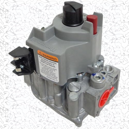
Figure 1: ClimaTek VR800A1178 Furnace Control Gas Valve. This image shows the gas valve from a frontal perspective, highlighting its main body, electrical connections, and gas inlet/outlet ports.
Key Features:
- Direct OEM upgraded replacement for VR800A1178.
- Ensures safe and controlled gas flow to the furnace burner.
- Integrated safety shut-off mechanism.
- Pressure regulation for optimal furnace performance.
- Durable construction for long-lasting reliability.
4. Setup and Installation
IMPORTANT: Installation of this gas valve requires specialized knowledge and tools. It must be performed by a qualified HVAC technician. Attempting to install this component without proper training can result in serious injury, property damage, or death.
General Installation Steps (for Qualified Technicians):
- Safety First: Turn off electrical power and main gas supply to the furnace.
- Access: Locate and access the existing gas valve within the furnace.
- Disconnect: Disconnect all electrical wiring and gas piping from the old valve. Be prepared for residual gas in the lines.
- Remove Old Valve: Carefully remove the old gas valve.
- Prepare New Valve: Apply appropriate pipe sealant to the threaded connections of the new ClimaTek VR800A1178 valve.
- Install New Valve: Install the new valve, ensuring it is oriented correctly and securely tightened.
- Reconnect: Reconnect all gas piping and electrical wiring according to the furnace manufacturer's specifications and wiring diagrams.
- Leak Test: Turn on the main gas supply and perform a thorough leak test on all gas connections using a suitable leak detection solution.
- Restore Power: Restore electrical power to the furnace.
- Test Operation: Follow the furnace manufacturer's instructions to test the operation of the furnace and the new gas valve, including ignition and safety shut-off functions.
- Adjustments: Make any necessary pressure adjustments as per furnace specifications.
5. Operating Principles
The ClimaTek VR800A1178 gas valve operates under the control of the furnace's integrated control board. When a call for heat is initiated by the thermostat, the control board sends a signal to the gas valve. The valve then opens, allowing gas to flow to the main burner. Simultaneously, the igniter (hot surface igniter or pilot light) is activated to ignite the gas.
The valve also incorporates safety features. If ignition fails or if a flame is not detected by the flame sensor, the gas valve will automatically close, shutting off the gas supply to prevent the accumulation of unburnt gas. This ensures safe operation and prevents hazardous conditions. The internal pressure regulator maintains a consistent gas pressure to the burner for efficient combustion.
6. Maintenance
The ClimaTek VR800A1178 gas valve itself typically requires no routine user maintenance. However, it is an integral part of your furnace system, which should undergo annual professional maintenance.
Recommended Maintenance Practices:
- Annual Professional Inspection: Have a qualified HVAC technician inspect your entire furnace system annually. This inspection should include checking the gas valve for proper operation, gas leaks, and any signs of wear or damage.
- Cleanliness: Ensure the area around the furnace and gas valve is kept clean and free of dust, debris, and obstructions.
- Air Filter Replacement: Regularly replace or clean your furnace's air filter as recommended by the furnace manufacturer to ensure proper airflow and system efficiency.
Do not attempt to lubricate or disassemble the gas valve. If the valve is malfunctioning, it should be replaced by a qualified technician.
7. Troubleshooting
This section provides general troubleshooting guidance. For safety and proper diagnosis, always contact a qualified HVAC technician for any issues related to your furnace's gas system.
| Symptom | Possible Cause | Action (for Qualified Technician) |
|---|---|---|
| Furnace not igniting / No heat | No gas supply to burner, faulty igniter, faulty flame sensor, gas valve malfunction, control board issue. | Check gas supply, inspect igniter and flame sensor, test gas valve operation and electrical connections, diagnose control board. |
| Gas odor near furnace | Gas leak from piping or valve, improper sealing. | IMMEDIATELY SHUT OFF GAS SUPPLY AND VENTILATE AREA. DO NOT OPERATE ANY ELECTRICAL SWITCHES. CONTACT GAS COMPANY AND QUALIFIED TECHNICIAN. Perform leak test. |
| Burner flame erratic or weak | Incorrect gas pressure, dirty burner, partially obstructed gas line, gas valve issue. | Check and adjust gas pressure, clean burner, inspect gas lines, test gas valve. |
| Furnace cycles on and off rapidly (short cycling) | Overheating, airflow issues, faulty thermostat, flame sensor issue, gas valve issue. | Check airflow, thermostat settings, flame sensor, and gas valve operation. |
If you suspect a gas leak, evacuate the premises immediately and contact your gas provider and emergency services from a safe location. Do not re-enter the building until it has been declared safe by authorities.
8. Specifications
- Model: ClimaTek VR800A1178
- Replaces: Honeywell VR800A1178
- Product Dimensions: 4 x 6 x 6 inches
- Item Weight: 2.19 pounds
- Manufacturer: HYWL (OEM for ClimaTek)
- ASIN: B0F8WQL2XR
- Application: Furnace Control Gas Valve
- Gas Type: Natural Gas / LP Gas (check specific valve labeling for compatibility)
- Electrical Requirements: (Typically 24VAC, refer to furnace wiring diagram)
Note: Specific operating pressures and electrical ratings are typically marked on the gas valve label. Always refer to the product label and furnace manufacturer's specifications for precise details.
9. Warranty and Support
ClimaTek products are manufactured to high-quality standards. For information regarding the warranty period and terms for your VR800A1178 Furnace Control Gas Valve, please refer to the documentation provided with your purchase or contact your authorized ClimaTek dealer or the seller directly.
For technical support, installation assistance, or to report a product issue, please contact the retailer from whom you purchased this product or visit the official ClimaTek website for contact information.
Online Resources:
- ClimaTek Store on Amazon
- For general HVAC information and professional assistance, consult local certified HVAC technicians.


