1. Introduction
This manual provides detailed instructions for the installation, operation, and maintenance of the ZKRZCGXZ ZK-SMC02 Stepper Motor Driver Controller. This integrated board is designed to control 42 and 57 series stepper motors, offering forward/reverse pulse, speed, and angle control capabilities. Please read this manual thoroughly before use to ensure proper and safe operation.
2. Safety Information
- Always disconnect power before making any wiring connections or disconnections.
- Ensure the input voltage is within the specified range (DC 5V-30V).
- Avoid touching the circuit board components when power is applied.
- Do not expose the device to moisture, extreme temperatures, or corrosive environments.
- Properly ground all components as required by local electrical codes.
3. Product Overview
The ZK-SMC02 features an intuitive control panel with a digital display, buttons for direction control, and a potentiometer for speed adjustment. The rear of the board provides terminals for motor and power connections, along with advanced configuration options.

Figure 3.1: Front view of the ZK-SMC02 Stepper Motor Driver Controller, showing the display, CW/CCW buttons, and potentiometer.

Figure 3.2: Rear view of the ZK-SMC02 Stepper Motor Driver Controller, highlighting the motor (A+, A-, B+, B-) and power (VCC, GND) terminals.
4. Setup
4.1 Power Supply and Motor Connection
Connect the stepper motor and power supply to the ZK-SMC02 board as shown in the diagram below. Ensure correct polarity for the power supply and proper phase connections for the motor.
- Power Input: Connect your DC 5V-30V power supply to the VCC (+) and GND (-) terminals.
- Motor Connection: Connect the stepper motor's A+, A-, B+, B- wires to the corresponding terminals on the board. Refer to your motor's specifications for correct phase identification.
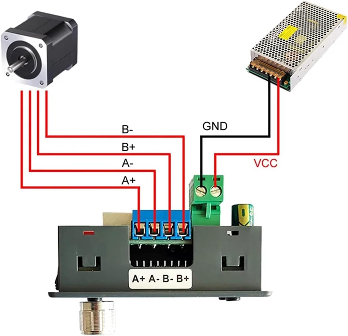
Figure 4.1: Basic wiring diagram showing connections for a stepper motor and a DC power supply to the ZK-SMC02 controller.
4.2 Advanced Settings (Subdivision and Current Adjustment)
The ZK-SMC02 allows for adjustment of motor subdivision and drive current. These settings are typically located on the underside or internal components of the board, accessible by removing the casing if necessary. Refer to the diagram below for details.
- Subdivision Setting: Use the DIP switches (S1, S2, S3) to set the desired micro-stepping resolution. The table below provides common settings.
- Current Adjustment: Use the potentiometer labeled 'Adjust current 0~4A' to set the motor drive current. Adjust carefully to match your motor's rated current.

Figure 4.2: Internal view showing subdivision DIP switches (S1, S2, S3) and the current adjustment potentiometer (0-4A). Also shows input control signal terminals and UART terminal.
Subdivision Settings Table
| S3 | S2 | S1 | M-SET (Subdivision) |
|---|---|---|---|
| ON | ON | ON | NC |
| OFF | ON | ON | 1 |
| ON | OFF | ON | 2/A |
| ON | ON | OFF | 2/B |
| OFF | OFF | ON | 4 |
| ON | OFF | OFF | 8 |
| OFF | ON | OFF | 16 |
| OFF | OFF | OFF | 32 |
5. Operating Instructions
The ZK-SMC02 features a user-friendly control panel for direct operation. Familiarize yourself with the buttons and display as labeled below.

Figure 5.1: Labeled control panel of the ZK-SMC02, indicating the Forward Button (CW), Reverse Button (CCW), Run/Stop Button, Potentiometer, Forward Indicator, Reverse Indicator, Rotating Speed display, and Delay Time or Cycle Times display.
5.1 Basic Operation
- Power On: Once connected to a power supply, the display will illuminate.
- Start/Stop: Press the RUN/STOP button to start or stop the motor.
- Change Direction: Press the CW button for clockwise rotation (forward) or the CCW button for counter-clockwise rotation (reverse). The corresponding indicator (Forward/Reverse) will light up.
- Adjust Speed/Angle: Rotate the Potentiometer knob to adjust the motor's rotating speed or angle. The display will show the current value.
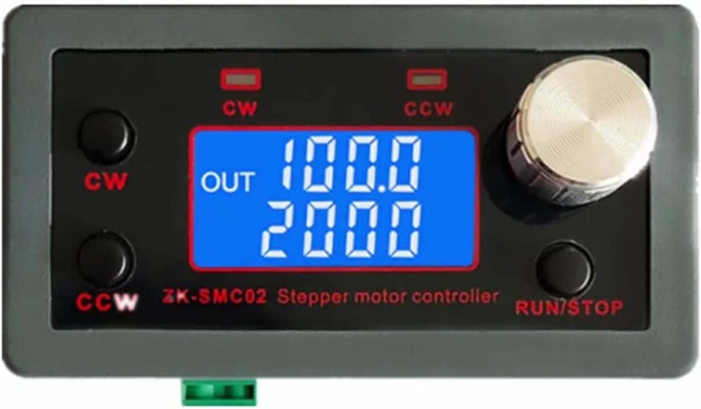
Figure 5.2: The ZK-SMC02 display during operation, showing output values (e.g., speed and pulse count).
5.2 Display Information
The digital display provides real-time feedback on the motor's operation:
- Rotating Speed: Indicates the current operational speed of the motor.
- Delay Time or Cycle Times: Depending on the selected mode (if applicable), this area displays either a delay timer or the number of cycles completed.
6. Maintenance
To ensure the longevity and reliable performance of your ZK-SMC02 controller, follow these general maintenance guidelines:
- Keep Clean: Regularly clean the device with a soft, dry cloth. Avoid using liquid cleaners or solvents.
- Environmental Conditions: Operate and store the controller in a dry, dust-free environment, away from direct sunlight and extreme temperatures.
- Check Connections: Periodically inspect all wiring connections to ensure they are secure and free from corrosion.
- Ventilation: Ensure adequate airflow around the device, especially if it is enclosed, to prevent overheating.
7. Troubleshooting
If you encounter issues with your ZK-SMC02 controller, refer to the following troubleshooting tips:
- No Power/Display Off:
- Check the power supply connection and ensure it is providing DC 5V-30V.
- Verify the power supply is functioning correctly.
- Motor Not Moving:
- Ensure the motor is correctly wired to the A+, A-, B+, B- terminals.
- Check if the motor drive current is set appropriately for your motor (0-4A).
- Verify the RUN/STOP button has been pressed to start operation.
- Confirm the motor itself is functional.
- Incorrect Motor Direction:
- Press the opposite direction button (CW or CCW).
- If the issue persists, check the motor phase wiring. Swapping A+ with A- or B+ with B- might reverse direction.
- Erratic Motor Movement:
- Check for loose wiring connections.
- Ensure the subdivision settings are appropriate for your application.
- Verify the power supply is stable and providing sufficient current.
8. Specifications
| Feature | Specification |
|---|---|
| Model | ZK-SMC02 |
| Input Voltage | DC 5V-30V |
| Compatible Motors | 42, 57 Series Stepper Motors |
| Adjustable Current | 0-4A |
| Control Functions | Forward/Reverse, Pulse Speed, Angle Control |
| Package Dimensions | 1.18 x 0.79 x 0.39 inches |
| Item Weight | 1.76 ounces |
| Manufacturer | ZKRZCGXZ |
9. Warranty and Support
Information regarding product warranty and customer support was not provided in the available product data. Please refer to the retailer or manufacturer's official website for specific warranty terms and support contact details.


