1. Introduction
This document provides detailed instructions for the ICSTATION DC 12V PWM 4-Wire Fan Speed Controller Module, Model GY21835-1. This device is a temperature-controlled fan speed regulator designed for 4-wire PWM fans. It allows for both automatic and manual adjustment of fan speed based on temperature readings, displayed in Celsius (℃). The module features a digital display showing both the current temperature and the fan’s rotational speed in RPM (revolutions per minute), aiming to optimize cooling performance and energy efficiency.

Figure 1: ICSTATION DC 12V PWM 4-Wire Fan Speed Controller Module with temperature probe.
2. Product Features
- Fan Speed Regulation: Controls 4-wire PWM fans based on temperature, offering automatic or manual speed adjustment.
- Digital Display: Shows current temperature (℃) and fan speed in RPM.
- RPM Display (X100RPM): Fan speed is displayed in units of 100 RPM. For example, “247” indicates 24,700 RPM. The maximum readable value is 300 × 100 RPM = 30,000 RPM.
- Dual Control Modes: Supports both manual and automatic fan speed control for versatile application.
- Temperature Probe: Equipped with a 42cm (16.54 inch) NTC10KB=3590 temperature probe for continuous and accurate thermal monitoring.
- Compact Design: Features a black shell panel for circuit protection and easy installation.

Figure 2: Overview of the fan speed controller’s key features.
3. Setup and Installation
Careful installation is crucial for proper function and safety. Please follow these guidelines:
- Compatibility: This controller is designed exclusively for 4-wire PWM fans. It does not support 2-wire or 3-wire fans. The PWM signal specification is 25KHz 5V.
- Voltage Matching: Ensure the working voltage supplied to the controller is equal to the fan’s operating voltage (typically 12V DC). Mismatched voltages can damage the fan or controller.
- Power Connection: Connect the DC 12V power supply to the designated input terminals on the controller. Observe correct polarity (VCC for positive, GND for negative).
- Fan Connection: Connect your 4-wire PWM fan to the fan output terminals. Ensure all four wires are correctly connected according to the wiring diagram.
- Temperature Probe Placement: Connect the NTC temperature sensor to its dedicated port. Position the temperature probe near the heat source or in the area where precise temperature monitoring is required. The 42cm cable provides flexibility for optimal placement.
4. Wiring Diagram
Refer to the diagram below for correct wiring connections of the fan speed controller.

Figure 3: Detailed wiring diagram for the ICSTATION fan speed controller.
- Input Voltage VCC / GND: Connect your 12V DC power supply here.
- Output Speed: This terminal provides the speed output.
- PWM Control Signal: Connects to the PWM control line of the 4-wire fan.
- Fan Speed Signal: Connects to the speed feedback line of the 4-wire fan.
- Fan Power VCC / GND: Provides power to the 4-wire fan.
- NTC: Connect the 10K B=3590 NTC temperature sensor here.
5. Operating Instructions
The controller offers two primary modes of operation: Manual Control and Automatic Control.
5.1 Display Information

Figure 4: The controller’s dual display showing temperature and RPM.
- When the “℃” light is illuminated, the display shows the current temperature.
- When the “X100RPM” light is illuminated, the display shows the current fan rotational speed in units of 100 RPM.
5.2 Control Modes

Figure 5: Illustration of manual and automatic control modes.
Manual Control Mode:
In the running state, press the OK button briefly to enter manual speed adjustment. Use the + and - buttons to set the fan speed percentage (ranging from 1-100%). Press OK again to save the setting and exit manual mode.
Automatic Control Mode:
To enter temperature parameter settings for automatic control, long-press the OK button. After configuring the settings, the device will automatically adjust the fan speed according to the set temperature parameters and real-time temperature readings from the probe.
Setting Parameters for Automatic Mode:
Long press the OK button for 2 seconds to enter the settings menu. Use + and - to navigate and adjust values, and OK to confirm and move to the next parameter.
- L (Low Temperature): This is the temperature at which the fan begins to run at its initial set speed.
- H (High Temperature): This is the temperature at which the fan will run at 100% speed. The range between L and H defines the temperature gradient for fan speed ramping. A minimum 5-degree difference between L and H is maintained.
- C (Cutoff Temperature): The fan will stop when the temperature falls below this value. A minimum 2-degree difference between C and L is maintained.
6. Maintenance
The ICSTATION fan speed controller is designed for low maintenance. Follow these general guidelines:
- Cleaning: Keep the module clean and free from dust. Use a soft, dry cloth for cleaning. Avoid using liquids or abrasive cleaners.
- Temperature Probe: Ensure the temperature probe is securely connected and positioned correctly. Periodically check for any physical damage to the probe or its cable. The probe is pluggable and replaceable if needed.
- Connections: Regularly inspect all wiring connections to ensure they are secure and free from corrosion.
- Environment: Operate the controller within its specified environmental conditions to ensure longevity.
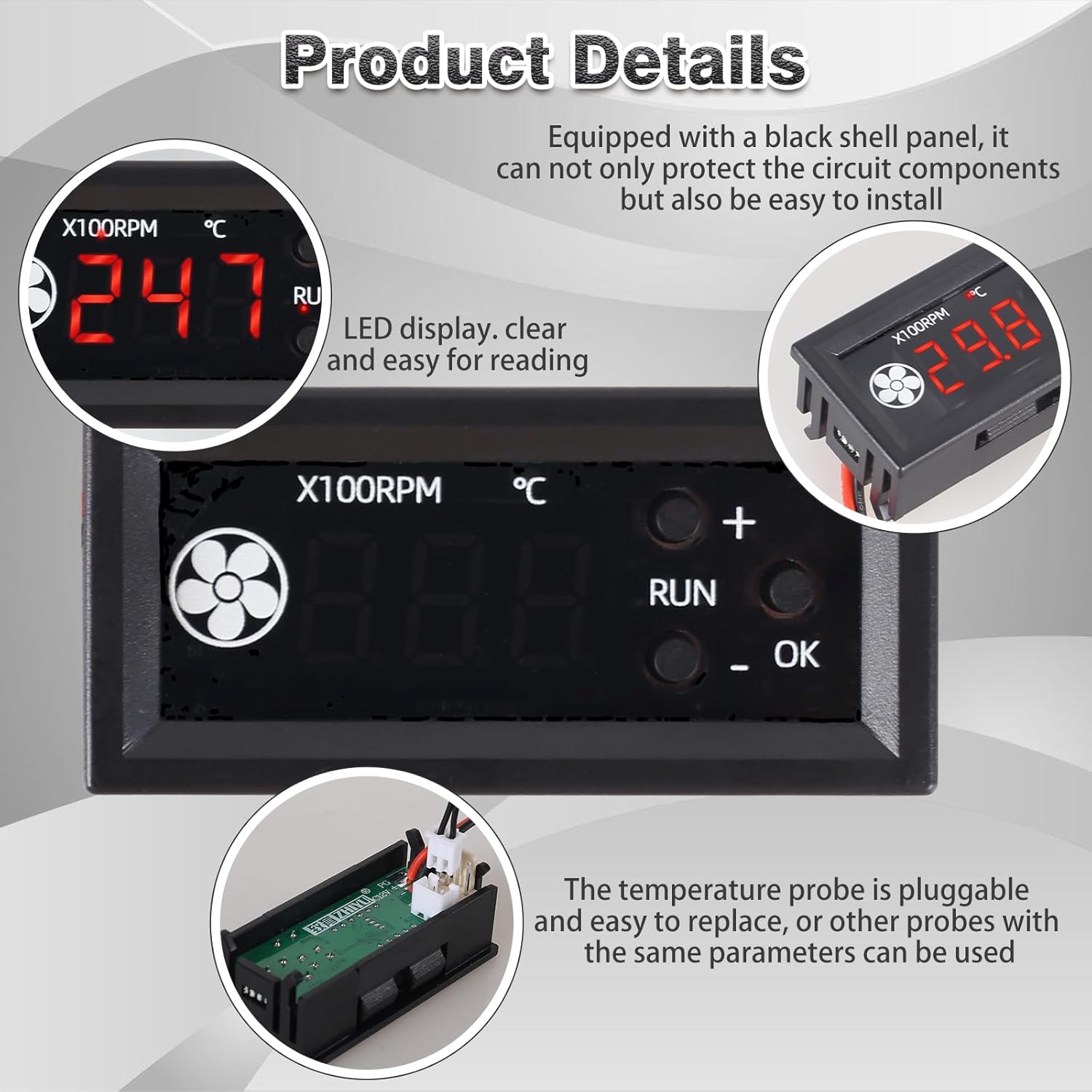
Figure 6: The controller features an LED display and a pluggable temperature probe for easy replacement.
7. Troubleshooting
If you encounter issues with your fan speed controller, consider the following:
- Fan Not Running or Incorrect Speed:
- Verify that the fan is a 4-wire PWM type. This controller is not compatible with 2-wire or 3-wire fans.
- Check that the input voltage to the controller matches the fan’s operating voltage (e.g., 12V DC).
- Ensure all wiring connections are secure and correctly matched according to the wiring diagram (Figure 3).
- In manual mode, check the set speed percentage. In automatic mode, verify the L, H, and C temperature settings.
- Incorrect Temperature Reading:
- Ensure the temperature probe is properly connected to the NTC port.
- Check the probe for any physical damage. If damaged, the probe is replaceable.
- Confirm the probe is positioned correctly to accurately sense the desired temperature.
- Display Not Working:
- Check the power supply connection to the controller.
- Ensure the input voltage is within the specified range (DC 12V).
- Fan Damage:
- As noted in user feedback, ensure the voltage supplied to the controller and fan does not exceed the fan’s maximum rated voltage, especially in systems with fluctuating voltage (e.g., lithium battery setups).
8. Specifications

Figure 7: Key technical parameters of the fan temperature controller.
| Parameter | Value |
|---|---|
| Model Number | GY21835-1 |
| Working Voltage | DC 12V |
| Fan Current | No more than 3.5A |
| PWM Range | 1-100 ± 0.5% |
| PWM Frequency | 25KHz (± 1KHz) |
| PWM Signal Amplitude | 5V (no-load) |
| Temperature Measurement Range | -9.9–99.9葑 |
| Temperature Measurement Error | Less than 1.2℃ (0-50℃), less than 2℃ (other ranges) |
| Operating Temperature (Max) | 99.9℃ |
| Product Dimensions | 3.15 x 1.8 x 0.5 inches (80 x 45 x 12.7 mm) |
| Item Weight | 0.634 ounces (18 grams) |
| Material | Plastic |
| Display Type | Digital LED |

Figure 8: Physical dimensions of the controller module.
9. Safety Information
- Always ensure the power supply is disconnected before making any wiring changes or performing maintenance.
- Verify correct voltage and polarity before powering on the device. Incorrect voltage can cause damage or fire.
- This device is intended for use with 4-wire PWM fans only. Do not attempt to connect 2-wire or 3-wire fans.
- Keep the device away from moisture, extreme temperatures, and corrosive environments.
- Do not open the casing or attempt to modify the internal circuitry, as this may void any warranty and pose safety risks.
10. Warranty and Support
For warranty information and technical support, please refer to the seller’s policies on the purchase platform or contact ICSTATION customer service directly. Keep your purchase receipt for warranty claims.