1. Introduction
This manual provides detailed instructions for the safe and efficient operation of your AGAGA WPS3010 Variable DC Power Supply. This miniature switching DC power supply offers precise control over output voltage and current, featuring a high-precision digital display for voltage, current, and power. It is designed for a wide range of applications requiring a stable and adjustable DC power source.
2. Safety Information
Always observe the following safety precautions to prevent injury or damage to the device:
- Ensure the power supply is connected to a properly grounded outlet.
- Do not operate the device in wet or damp conditions.
- Avoid short-circuiting the output terminals.
- Do not open the casing; there are no user-serviceable parts inside. Refer servicing to qualified personnel.
- Ensure proper ventilation to prevent overheating. The device includes a cooling fan.
- Verify the input voltage selector switch (115V/230V) is set correctly for your region before connecting to power.
- This unit features Over Voltage Protection (OVP), Over Current Protection (OCP), and Over Temperature Protection. However, always operate within specified limits.
3. Product Overview
Familiarize yourself with the components and controls of your AGAGA WPS3010 DC Power Supply.
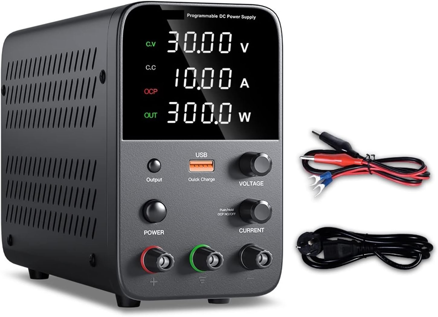
Figure 3.1: Front view of the AGAGA WPS3010 DC Power Supply, showing the digital display, USB quick charge port, voltage and current adjustment knobs, output switch, power switch, and output terminals.
3.1 Front Panel Controls and Indicators
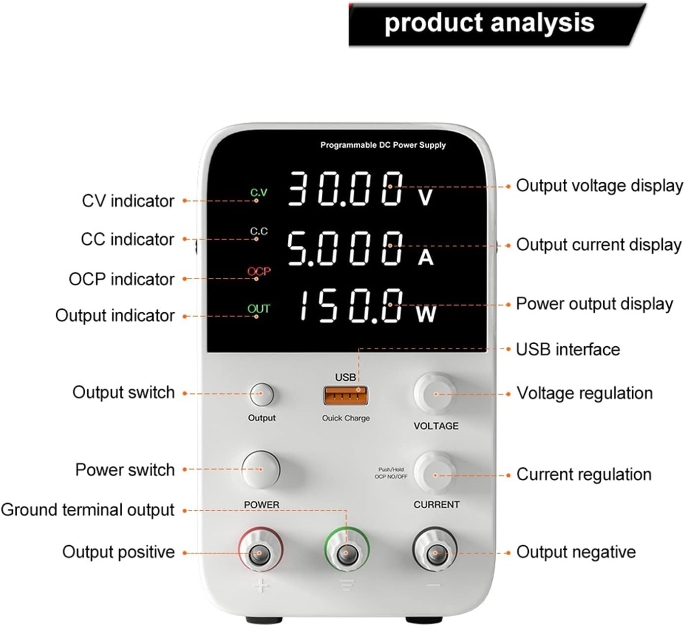
Figure 3.2: Detailed breakdown of the front panel, highlighting the Output Voltage Display, Output Current Display, Power Output Display, USB Interface, Voltage Regulation knob, Current Regulation knob, Output Switch, Power Switch, Ground Terminal Output, Output Positive, Output Negative, CV indicator, CC indicator, and OCP indicator.
- Output Voltage Display: Shows the current output voltage in Volts (V).
- Output Current Display: Shows the current output current in Amperes (A).
- Power Output Display: Shows the calculated output power in Watts (W).
- USB Interface: For quick charging compatible devices.
- Voltage Regulation Knob: Adjusts the output voltage. Press the knob to switch digits for fine adjustment.
- Current Regulation Knob: Adjusts the output current limit. Press the knob to switch digits for fine adjustment.
- Output Switch: Toggles the power output on/off.
- Power Switch: Main power on/off for the unit.
- Output Terminals (+, -, Ground): Connect your load here.
- CV Indicator: Illuminates when the unit is operating in Constant Voltage mode.
- CC Indicator: Illuminates when the unit is operating in Constant Current mode.
- OCP Indicator: Illuminates when Over Current Protection is active.
3.2 Rear Panel Features
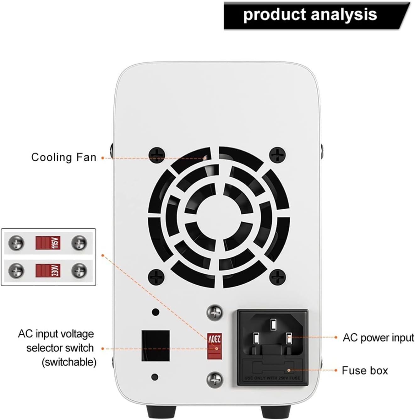
Figure 3.3: Rear panel view, showing the Cooling Fan, AC Input Voltage Selector Switch (switchable between 115V and 230V), AC Power Input socket, and Fuse Box.
- Cooling Fan: Dissipates heat to maintain optimal operating temperature.
- AC Input Voltage Selector Switch: Allows selection between 115V and 230V AC input. Ensure this is set correctly for your local power grid before connecting.
- AC Power Input: Connect the provided power cord here.
- Fuse Box: Contains the protective fuse.
4. Setup
- Unpacking: Carefully remove the power supply and all accessories from the packaging. Verify all items listed in Section 9 (Package Contents) are present.
- Placement: Place the power supply on a stable, flat surface with adequate ventilation around the unit, especially at the rear where the cooling fan is located. Avoid placing it near heat sources or in direct sunlight.
- Input Voltage Selection: Before connecting the power cord, check the AC Input Voltage Selector Switch on the rear panel. Set it to either 115V or 230V to match your local mains voltage. Incorrect setting can damage the unit.
- Power Connection: Connect the provided power cord to the AC Power Input socket on the rear panel and then plug the other end into a grounded wall outlet.
- Initial Power On: Turn on the main Power Switch on the front panel. The digital display should illuminate.
5. Operating Instructions
5.1 Setting Voltage and Current

Figure 5.1: Illustrates how to adjust voltage and current by pressing and turning the respective knobs to set individual digits.
- Setting Voltage:
- Turn the Voltage Regulation Knob to set the desired output voltage.
- For fine adjustment, press the Voltage Regulation Knob. This will highlight a digit on the voltage display. Turn the knob to change the value of the highlighted digit (0-9). Press again to move to the next digit.
- Setting Current Limit:
- Turn the Current Regulation Knob to set the desired maximum output current. This acts as a current limit.
- Similar to voltage, press the Current Regulation Knob to select and adjust individual digits for precise current limit setting.
- Pre-setting without Short Circuit: You can set the voltage and current limits before connecting a load or enabling output. This is a safe practice to prevent accidental over-voltage or over-current to your circuit.
5.2 Connecting a Load and Outputting Power
- Ensure the Output Switch is in the OFF position.
- Connect your load to the output terminals using the provided test leads. Connect the positive (+) terminal of the power supply to the positive input of your load, and the negative (-) terminal to the negative input of your load. If grounding is required, connect to the ground terminal.
- Set the desired voltage and current limits as described in Section 5.1.
- Once connections are secure and settings are verified, press the Output Switch to enable power output. The display will show the actual voltage, current, and power being delivered to the load.
- To stop output, press the Output Switch again.
5.3 Constant Voltage (CV) and Constant Current (CC) Modes
The power supply automatically switches between Constant Voltage (CV) and Constant Current (CC) modes depending on the load and your set limits:
- Constant Voltage (CV) Mode: When the load resistance is high, the power supply maintains the set output voltage, and the current drawn by the load will be less than or equal to the set current limit. The CV indicator will be lit.
- Constant Current (CC) Mode: When the load resistance is low, causing the current to reach the set current limit, the power supply will automatically reduce the output voltage to maintain the set current. The CC indicator will be lit. This protects both the power supply and the connected load from overcurrent.
5.4 USB Quick Charge Function
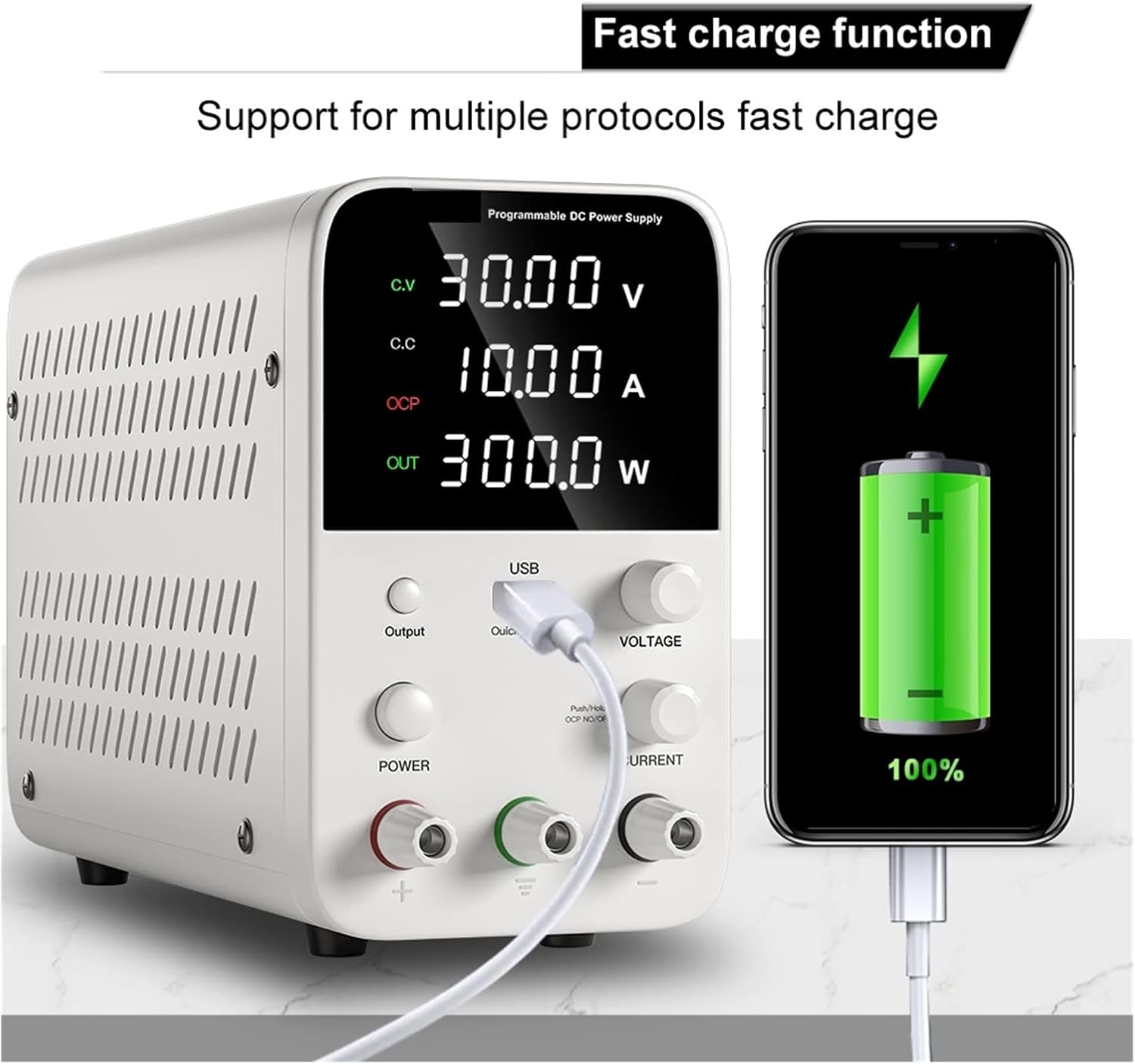
Figure 5.2: The power supply's USB port providing fast charging to a mobile phone, demonstrating its support for multiple fast charge protocols.
The integrated USB port supports multiple fast charge protocols, allowing you to conveniently charge compatible devices like smartphones and tablets directly from the power supply.
6. Applications
The AGAGA WPS3010 Variable DC Power Supply is versatile and suitable for a wide range of applications, including but not limited to:

Figure 6.1: Examples of the power supply's broad applicability in DIY laboratories, school laboratories, factory assembly lines, and appliance repair.
- Production line testing.
- Mobile phone, computer, and electrical appliance maintenance.
- Product aging tests for components like resistors, capacitors, relays, DC motors, and LEDs.
- Battery charging.
- Laboratory research and teaching.
- Factory and maintenance power supply.
- Any other occasion requiring a stable and adjustable DC power supply.
7. Maintenance
Proper maintenance ensures the longevity and reliable operation of your power supply:
- Cleaning: Disconnect the power supply from the mains before cleaning. Use a soft, dry cloth to wipe the exterior. Do not use abrasive cleaners or solvents.
- Ventilation: Ensure the cooling fan and ventilation openings are free from dust and obstructions. Periodically clean dust from the fan area using compressed air if necessary, ensuring the unit is unplugged.
- Storage: When not in use for extended periods, store the power supply in a cool, dry place, away from direct sunlight and excessive humidity.
- Fuse Replacement: If the unit does not power on, check the fuse in the fuse box on the rear panel. Replace it only with a fuse of the same type and rating (refer to specifications). Always disconnect power before replacing the fuse.
8. Troubleshooting
This section addresses common issues you might encounter:
| Problem | Possible Cause | Solution |
|---|---|---|
| Unit does not power on. | No power from outlet; Power cord not connected; Power switch off; Blown fuse. | Check wall outlet; Ensure power cord is securely connected; Turn on Power Switch; Check and replace fuse if necessary (refer to Section 7). |
| No output voltage/current. | Output switch off; Incorrect voltage/current settings; OCP activated; Load disconnected or faulty. | Press Output Switch to ON; Adjust voltage/current knobs; Check if OCP indicator is lit and reduce current demand or increase current limit; Verify load connection and functionality. |
| Voltage/Current display is unstable. | Poor connection; Unstable load; Interference. | Check all connections; Ensure load is stable; Relocate unit away from strong electromagnetic interference. |
| Unit overheats. | Blocked ventilation; Excessive load. | Ensure cooling fan and vents are clear; Reduce load or operating time; Ensure ambient temperature is within limits. |
| OCP indicator is lit frequently. | Current limit set too low; Load drawing too much current. | Increase the current limit setting (Current Regulation Knob); Verify the current requirements of your load. |
9. Specifications
| Parameter | Value |
|---|---|
| Model | WPS3010 |
| Output Power | 300W (for WPS3010 variant) |
| Output Voltage | 0~30V (continuously adjustable) |
| Output Current | 0~10A (continuously adjustable) |
| Voltage Stability (CV) | 0.1% ±3mV |
| Load Stability (CV) | 0.2% ±3mV |
| Ripple Voltage (CV) | 0.5% Vp-p |
| Current Stability (CC) | 0.1% ±3mA |
| Load Stability (CC) | 0.2% ±3mA |
| Ripple Current (CC) | 0.5% Vp-p |
| Recovery Time | 500µS |
| Temperature Coefficient | 100ppm/°C |
| Operating Temperature | 0-40°C |
| Relative Humidity | <80% RH |
| Storage Temperature | -10-70°C |
| Storage Humidity | <70% RH |
| Dimensions (L x W x H) | Approx. 220mm x 90mm x 145mm (based on image 61M53nOTN5L.jpg) |
| Item Weight | 1.76 ounces (50 Grams) |
| Item Model Number | 180583831 |
| Manufacturer | AGAGA |
| Country of Origin | China |
10. Package Contents
The following items are included in the package:
- 1x AGAGA WPS3010 DC Power Supply
- 1x Power Cord
- 1x Test Line (leads)
- 1x Instructions (this manual)
11. Warranty and Support
For warranty information and technical support, please refer to the documentation provided with your purchase or contact the manufacturer directly. Specific warranty terms and support channels may vary by region and retailer.