
1. Introduction
This manual provides detailed instructions for the installation, operation, and maintenance of the amiciSmart 380V 60A Digital Timer Switch. This device is designed for precise control of high-power appliances in three-phase systems, offering programmable ON/OFF events to enhance safety, improve efficiency, and reduce operational costs. Please read this manual thoroughly before installation and use to ensure proper function and safety.
2. Product Overview
2.1 Key Features
- Heavy-Duty 3-Phase Control: Designed for loads up to 60A, suitable for industrial machinery, motors, heaters, and pumps.
- Wide Range Programming: Up to 32 ON/OFF schedules daily or weekly, with timing from 1 minute to 168 hours.
- 380V AC Operation: Compatible with three-phase 380V power systems at 50Hz.
- LCD Display: Clear digital screen for real-time status and programming.
- AA Battery Backup: Includes 1x AA battery to retain settings during power outages.
- Energy-Saving Automation: Automates equipment operation to optimize energy consumption and extend device lifespan.
2.2 Package Contents
- 1 x amiciSmart 380V 60A Digital Timer Switch
2.3 Internal Components and Applications
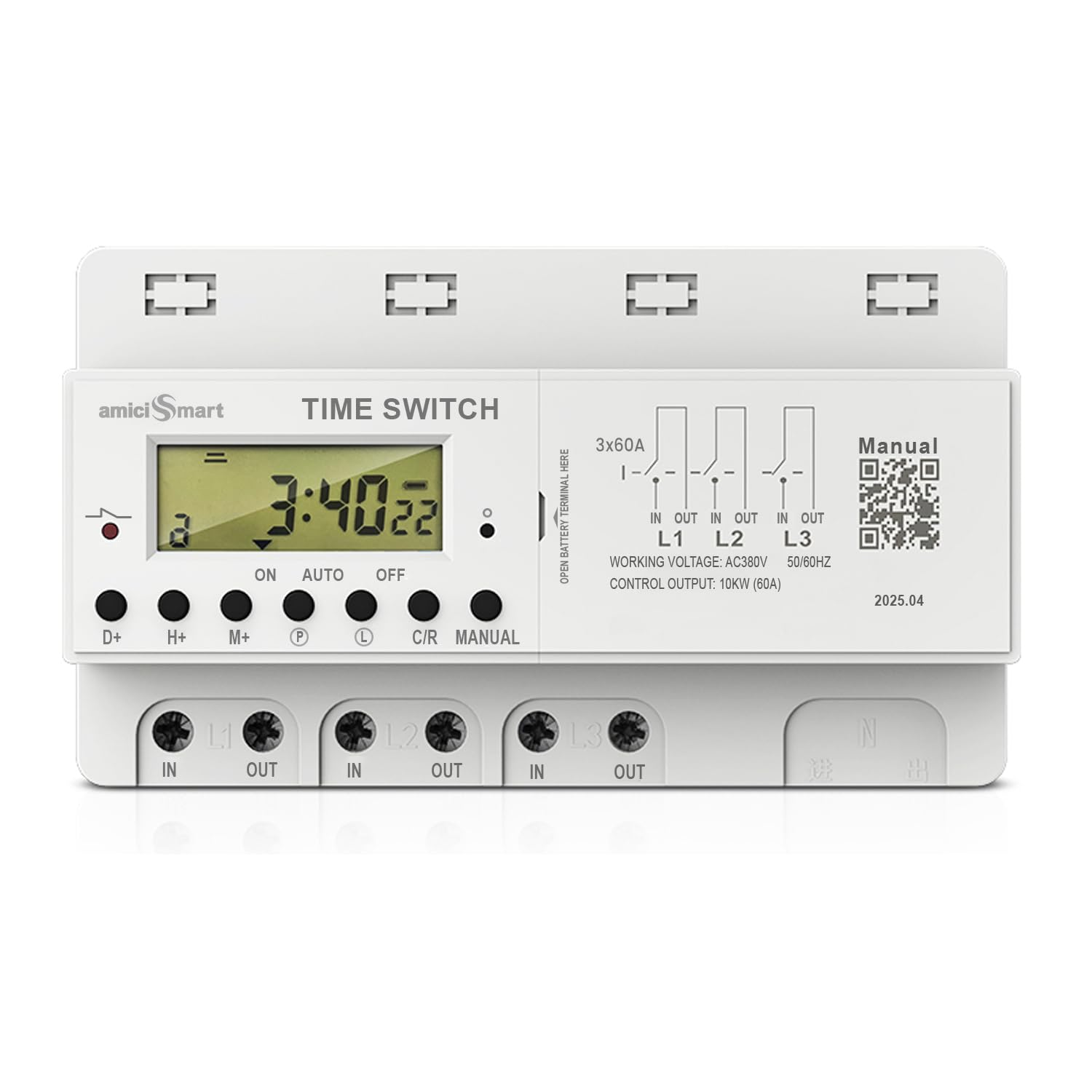
Image 2.3.1: Internal view of the timer switch, highlighting heavy-duty 60A terminals, individual 60A relays for each phase, and a copper wound transformer designed to manage voltage fluctuations. The image also illustrates typical applications such as automating 3-phase exhaust fans for factories, 3-phase HVAC systems, and agricultural motors.
3. Setup and Installation
Warning: Installation should only be performed by a qualified electrician. Ensure power is disconnected at the main circuit breaker before beginning any wiring work. This device operates on 380V AC and handles high currents; improper installation can lead to electric shock, fire, or equipment damage.
3.1 Physical Dimensions

Image 3.1.1: The timer switch measures approximately 15.4 cm in length, 8.8 cm in width, and 6.8 cm in height. Its weight is 580 grams. These dimensions ensure it can fit into standard electrical enclosures.

Image 3.1.2: The timer switch is designed to fit conveniently within a standard MCB (Miniature Circuit Breaker) distribution box, allowing for integrated and secure installation.
3.2 Wiring Diagram (Neutral-Free)
This timer switch is designed for three-phase systems and operates without requiring a neutral connection. It supports 230V per phase, totaling 380V AC between phases.

Image 3.2.1: The wiring terminals are clearly labeled for input (IN) and output (OUT) for each of the three phases (L1, L2, L3). This model is designed for a neutral-free three-phase supply. An easily replaceable AA battery compartment is located on the side for backup power.
- Identify the three incoming phase lines (L1, L2, L3) from your 380V AC supply.
- Connect the incoming phase lines to the corresponding 'IN' terminals (L1 IN, L2 IN, L3 IN) on the timer switch.
- Connect the load's three phase lines to the corresponding 'OUT' terminals (L1 OUT, L2 OUT, L3 OUT) on the timer switch.
- Ensure all connections are secure and properly insulated.
- Install the AA battery into the designated compartment to enable settings retention during power interruptions.
4. Operating Instructions
The timer switch features an LCD display and several buttons for programming. Refer to the device's front panel for button layout.

Image 4.0.1: The front panel displays the current time and operational status (ON/AUTO/OFF). Control buttons include D+ (Day), H+ (Hour), M+ (Minute), P (Program), C/R (Cancel/Recall), and MANUAL. A simplified wiring diagram is also printed on the device.
4.1 Setting Current Time
- Press the D+ button to set the current day of the week.
- Press the H+ button to set the current hour.
- Press the M+ button to set the current minute.
- The display will automatically save the time after a few seconds of inactivity.
4.2 Programming ON/OFF Events
The timer supports up to 32 ON/OFF programs. Each program consists of an ON time and an OFF time.
- Press the P button once to enter program setting mode. The display will show "1 ON".
- Use D+, H+, and M+ buttons to set the desired ON time for the first program.
- Press P again. The display will show "1 OFF".
- Use D+, H+, and M+ buttons to set the desired OFF time for the first program.
- Repeat steps 1-4 for additional ON/OFF programs (up to 32).
- To exit program setting mode, press the C/R button.
4.3 Manual Control
The MANUAL button allows you to override the programmed settings temporarily.
- Press MANUAL repeatedly to cycle through modes: ON (always on), AUTO (follows programs), OFF (always off).
- In AUTO mode, the timer will execute the programmed ON/OFF events.
4.4 Resetting the Device
To clear all settings and reset the timer to factory defaults, locate the small reset button (often recessed) and press it using a pointed object (e.g., a pen tip). This will erase all programmed times and reset the current time.
5. Maintenance
5.1 Cleaning
Wipe the exterior of the timer switch with a soft, dry cloth. Do not use abrasive cleaners, solvents, or immerse the device in water. Ensure the device is powered off before cleaning.
5.2 Battery Replacement
The timer switch uses one AA battery for backup power to retain settings during power outages. If the display becomes dim or settings are lost frequently, replace the battery.
- Ensure the main power supply to the timer is disconnected.
- Locate the battery compartment on the side of the device (refer to Image 3.2.1).
- Open the compartment cover and remove the old AA battery.
- Insert a new AA battery, observing correct polarity (+/-).
- Close the battery compartment cover securely.
6. Troubleshooting
| Problem | Possible Cause | Solution |
|---|---|---|
| Device does not power on. | No power supply; incorrect wiring. | Check main power supply. Verify wiring connections (L1, L2, L3 IN). Consult a qualified electrician. |
| Settings are lost after power outage. | AA backup battery is dead or missing. | Replace the AA backup battery. Ensure correct polarity. |
| Programs are not executing. | Timer is in MANUAL ON/OFF mode; incorrect program settings; current time is wrong. | Ensure the timer is in AUTO mode using the MANUAL button. Verify program ON/OFF times and days. Check and correct the current time. |
| Load does not turn ON/OFF. | Faulty load; incorrect wiring to load; timer malfunction. | Test the load independently. Verify wiring to load (L1, L2, L3 OUT). If issues persist, contact support. |
7. Specifications
| Feature | Detail |
|---|---|
| Display | LCD display |
| Working Voltage | 380V AC |
| Control Power | 60A |
| Frequency | 50Hz |
| Consumption Power | <1.5VA(A) |
| Timer Range | 1 minute ~ 168 hours |
| Working Temperature | -20℃ to 55℃ |
| Timing Times | 32 ON/OFF (day/week) |
| Battery | 1x AA Battery (for backup) |
| Material | Acrylonitrile Butadiene Styrene |
| Item Weight | 580 Grams |
| Model Number | AS-TIMER-3P-N |
| Country of Origin | China |
8. Warranty and Support
8.1 Warranty Information
The amiciSmart 380V 60A Digital Timer Switch comes with a 1-year warranty. Please retain your purchase receipt for warranty claims.
8.2 Customer Support
For technical assistance, warranty claims, or any product-related inquiries, please contact amiciKart customer support:
- Contact Number: +91 980 979 9898
- Email: care@amicikart.com