1. Introduction
This manual provides comprehensive instructions for the installation, operation, and maintenance of your YYTDNGW B9 Kit X99 Motherboard and Xeon E5 2650 V4 CPU Processor Set. Please read this manual carefully before proceeding with installation to ensure proper setup and optimal performance. This kit is designed for desktop applications, offering robust performance for gaming, audio/video editing, office tasks, and mini PC builds.
2. Package Contents
Verify that all items are present and in good condition upon opening the package. If any items are missing or damaged, contact your vendor immediately.
- YYTDNGW B9 Kit X99 Motherboard
- Intel Xeon E5 2650 V4 CPU Processor
- 16GB DDR4 ECC RAM Module
- SATA Cables
- I/O Shield
- User Manual (this document)
- Driver CD/USB (if applicable)
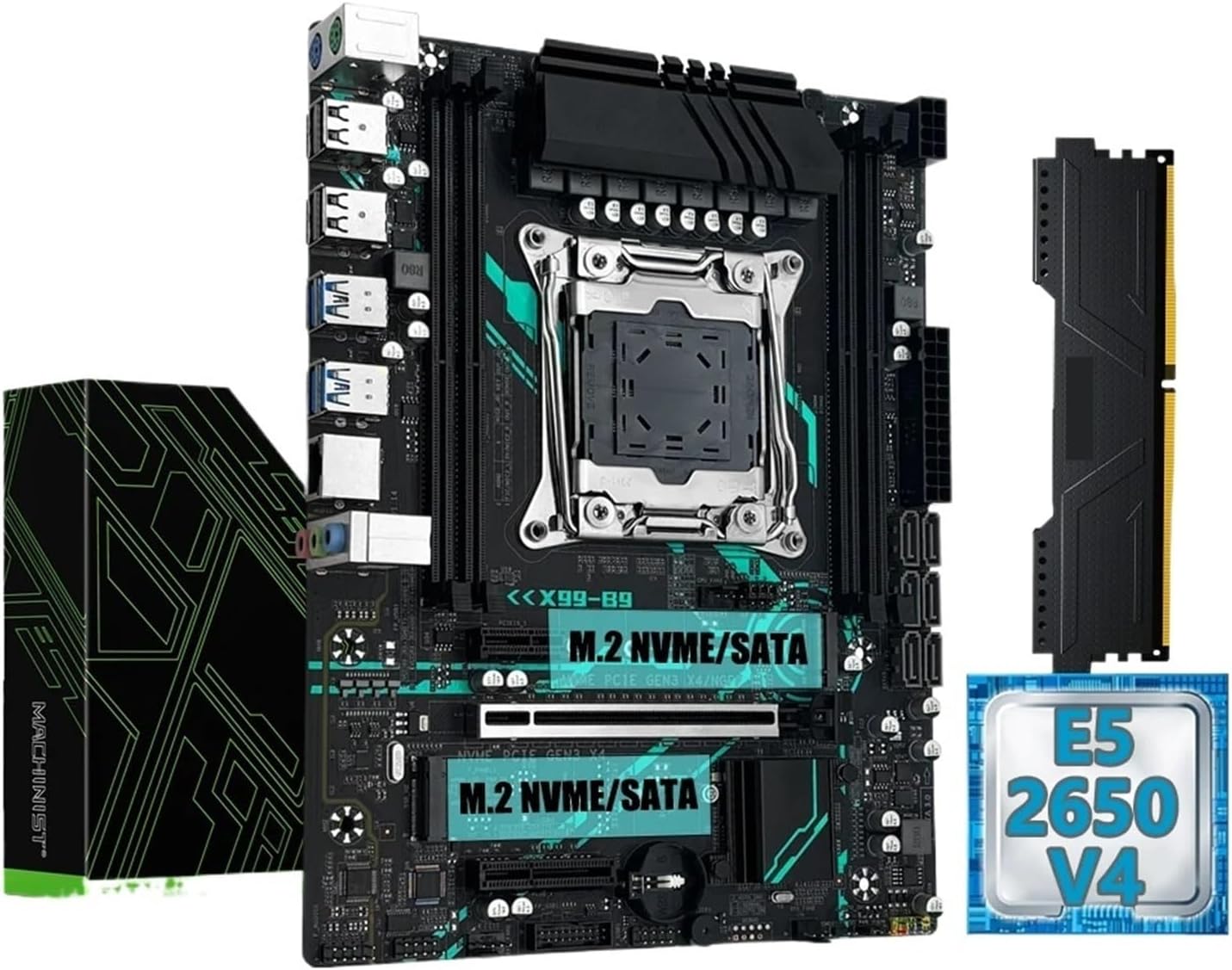
Figure 1: Main components of the YYTDNGW B9 Kit, including the X99 motherboard, Xeon E5 2650 V4 CPU, and a DDR4 RAM module.
3. Product Overview
The YYTDNGW B9 Kit X99 Motherboard is designed to support Intel LGA 2011-3 processors, including the included Xeon E5 2650 V4. It features a robust set of interfaces for high-performance computing.
Key Features:
- Processor Compatibility: LGA 2011-3 socket, compatible with Xeon E5 series processors.
- Memory Support: 4 DDR4 ECC memory slots, supporting up to 128GB total capacity with dual-channel architecture.
- Storage Interfaces: Dual M.2 NVMe/SATA slots (2280 size) and 6 SATA 3 ports for flexible storage configurations.
- Expansion Slots: 1 PCIe x16 slot (PCI-E 3.0), 1 PCIe x4 slot, and 1 PCIe x1 slot for graphics cards and other expansion cards.
- Connectivity: Onboard 1000Mbps LAN (1x RJ45), USB 3.0 and USB 2.0 ports (both internal headers and back I/O), 3 audio jacks, and PS/2 port.

Figure 2: Angled view of the YYTDNGW X99 motherboard, highlighting the CPU socket, RAM slots, and various connectors.
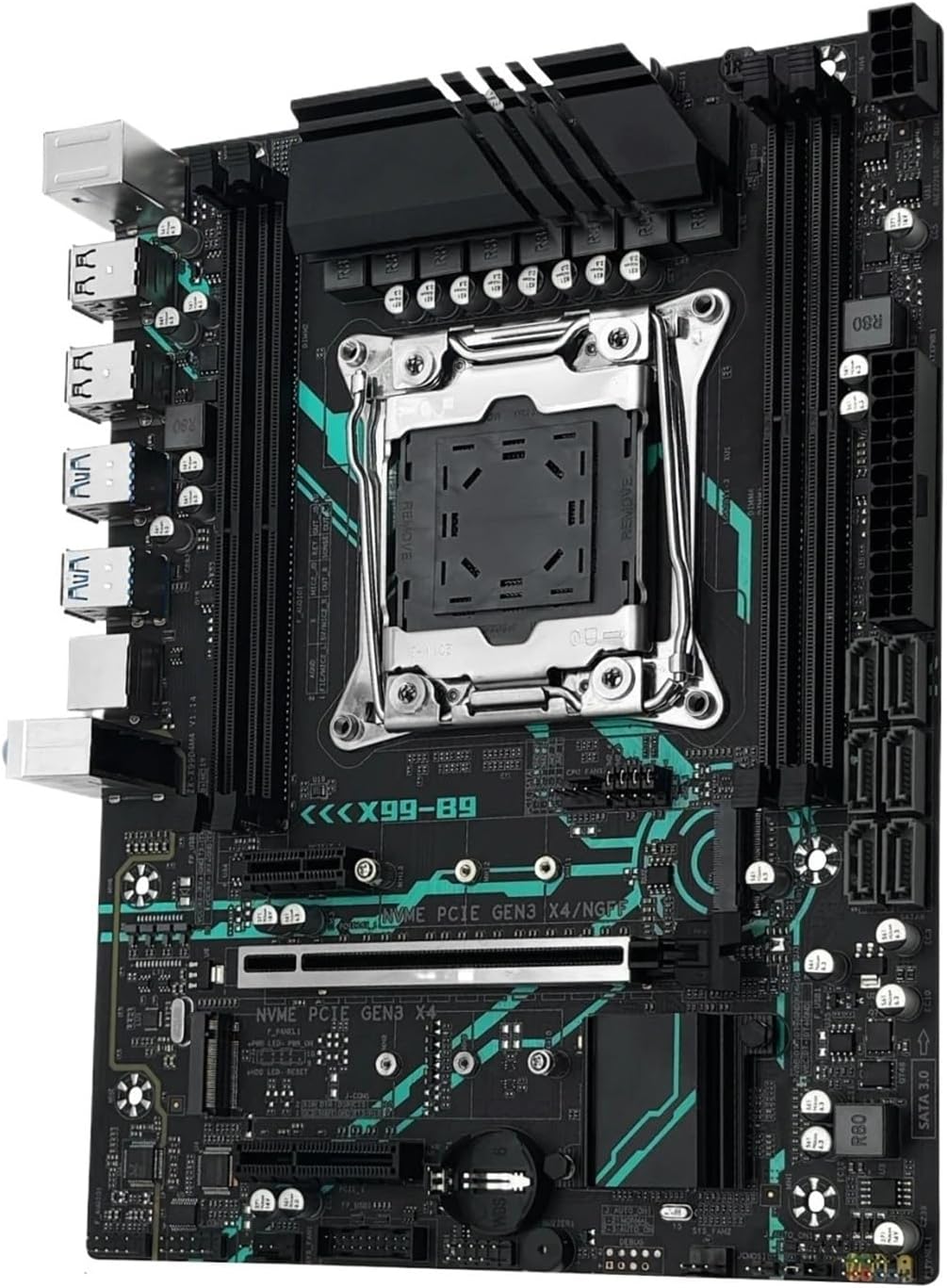
Figure 3: Detailed view of the motherboard's LGA 2011-3 CPU socket, DDR4 memory slots, and dual M.2 NVMe/SATA slots.
4. Setup Instructions
Before beginning installation, ensure your workspace is clean, well-lit, and free of static electricity. Use an anti-static wrist strap if available.
4.1. Motherboard Installation
- Prepare your PC case by installing the necessary standoffs for the Micro-ATX form factor.
- Carefully place the I/O shield into the rear opening of your PC case.
- Align the motherboard with the standoffs and gently lower it into place.
- Secure the motherboard with screws, ensuring not to overtighten.
4.2. CPU Installation (Xeon E5 2650 V4)
- Locate the LGA 2011-3 CPU socket on the motherboard.
- Open the CPU socket retention mechanism by pushing down and out on the lever(s).
- Carefully align the Xeon E5 2650 V4 CPU with the socket, matching the golden triangle/arrow on the CPU with the corresponding mark on the socket. Do not force the CPU into the socket.
- Gently lower the CPU into the socket.
- Close the retention mechanism by pushing the lever(s) back into place until they click.
- Apply a thin, even layer of thermal paste to the top of the CPU.
- Install your CPU cooler according to its manufacturer's instructions, ensuring proper contact and secure mounting.
4.3. RAM Installation (DDR4 ECC)
- Locate the 4 DDR4 memory slots. For dual-channel operation, refer to your motherboard's specific manual for recommended slot pairing (e.g., A1 and B1).
- Open the clips at both ends of the memory slot.
- Align the notch on the DDR4 memory module with the key in the memory slot.
- Press down firmly on both ends of the memory module until the clips snap into place.
4.4. Storage Device Installation (M.2 NVMe/SATA & SATA)
4.4.1. M.2 SSD Installation
- Locate the M.2 slots on the motherboard.
- Remove the M.2 standoff screw from the desired slot.
- Insert the M.2 SSD into the slot at a 30-degree angle, ensuring the gold contacts are fully seated.
- Gently push down the M.2 SSD and secure it with the standoff screw.
4.4.2. SATA Drive Installation
- Connect one end of a SATA data cable to a SATA port on the motherboard.
- Connect the other end of the SATA data cable to your SATA hard drive or SSD.
- Connect a SATA power cable from your power supply to the SATA hard drive or SSD.
4.5. Graphics Card Installation (PCIe x16)
- Locate the PCIe x16 slot.
- Remove the corresponding expansion slot cover from your PC case.
- Open the retention clip at the end of the PCIe x16 slot.
- Align your graphics card with the slot and press down firmly until it is fully seated and the retention clip snaps into place.
- Secure the graphics card to the case with a screw.
- Connect any necessary PCIe power cables from your power supply to the graphics card.
4.6. Power Connections
- Connect the 24-pin ATX main power connector from your power supply to the motherboard.
- Connect the 8-pin +12V CPU power connector (or 4-pin if applicable) from your power supply to the motherboard.
- Connect any additional power cables for graphics cards or other components.
4.7. Front Panel Connections
Connect the front panel cables from your PC case (Power LED, HDD LED, Power Switch, Reset Switch, USB 2.0, USB 3.0, Audio) to their respective headers on the motherboard. Refer to the motherboard's silkscreen labels for correct pin orientation.
5. Operating Instructions
5.1. First Boot-Up
- After completing all hardware installations, connect your monitor, keyboard, and mouse.
- Connect the power cord to your power supply and turn on the power switch on the PSU.
- Press the power button on your PC case.
- The system should power on and display the BIOS/UEFI splash screen.
- If no display, refer to the Troubleshooting section.
5.2. BIOS/UEFI Setup
During the initial boot sequence, press the designated key (usually DEL, F2, or F10) to enter the BIOS/UEFI setup utility. Here you can configure boot order, system time, and other advanced settings. Save changes before exiting.
5.3. Operating System Installation
Insert your operating system installation media (USB drive or DVD) and follow the on-screen prompts to install your preferred operating system. Ensure all necessary drivers (chipset, LAN, audio, etc.) are installed after the OS installation for optimal performance.
6. Maintenance
- Dust Removal: Regularly clean dust from inside your PC case, especially from fans and heatsinks, using compressed air. Ensure the system is powered off and unplugged before cleaning.
- BIOS/UEFI Updates: Periodically check the manufacturer's website for BIOS/UEFI updates. Updates can improve stability, compatibility, and performance. Follow update instructions carefully.
- Driver Updates: Keep your operating system and hardware drivers updated to ensure compatibility and optimal performance.
- Environmental Conditions: Operate the system in a well-ventilated area, away from direct sunlight, excessive heat, humidity, and dust.
7. Troubleshooting
- No Power:
- Check if the power supply is connected and switched on.
- Ensure all power cables (24-pin ATX, 8-pin CPU, GPU) are securely connected.
- Verify front panel power switch connection to the motherboard.
- No Display:
- Ensure the monitor is connected to the graphics card (or integrated graphics, if applicable) and powered on.
- Reseat the graphics card and RAM modules.
- Try booting with only one RAM stick.
- Check CPU cooler installation.
- System Instability/Crashes:
- Check CPU and GPU temperatures.
- Verify RAM is correctly seated and functioning (run memory diagnostic).
- Ensure all drivers are up to date.
- Check for loose cables.
- Operating System Not Booting:
- Check boot order in BIOS/UEFI.
- Verify storage drive connections.
- Run a diagnostic on the storage drive.
8. Specifications
| Brand | YYTDNGW |
| Model | B9 Kit X99 Motherboard |
| Form Factor | Micro-ATX |
| CPU Socket | LGA 2011-3 |
| Compatible Processors | Xeon E5 series (e.g., E5 2650 V4 included) |
| Chipset | C612 |
| Memory Slots | 4 x DDR4 ECC |
| Max Memory Capacity | 128 GB |
| Memory Channel | Double |
| Storage Interface | 2 x M.2 (NVMe/SATA 2280), 6 x SATA 3 |
| PCIe Slots | 1 x PCIe x16 (PCI-E 3.0), 1 x PCIe x4, 1 x PCIe x1 |
| Onboard LAN | 1 x RJ45 (1000Mbps) |
| Back I/O Ports | 1 x RJ45, 3 x Audio Jacks, 4 x USB 2.0, PS/2 |
| Onboard Connectors | 24-pin Main Power, CPU Fan, 4-pin +12V Power, 8-pin +12V Power, USB 3.0, USB 2.0 |
| Quality Certification | CE, RoHS |
9. Warranty and Support
For warranty information and technical support, please refer to the documentation provided with your purchase or contact your vendor directly. Keep your proof of purchase for warranty claims.


