1. Introduction
This manual provides essential instructions for the safe installation, operation, and maintenance of your GHHSBO ZA-D12 Variable Frequency Drive (VFD). The VFD is designed to control the speed of AC motors by varying the frequency and voltage of the power supplied to the motor. Please read this manual thoroughly before attempting to install or operate the device to ensure proper function and prevent damage or injury.
2. Safety Information
WARNING: Risk of electrical shock. Always read the user manual before operation. Disconnect all power sources and wait at least 10 minutes after removing power before servicing to allow capacitors to discharge. Only qualified personnel should perform installation and maintenance.
- Ensure the VFD is properly grounded.
- Do not operate the VFD with damaged cables or if the enclosure is open.
- Protect the VFD from moisture, dust, and corrosive gases.
- Verify input voltage matches the VFD's specifications before connecting power.

Image 2.1: Front view of the GHHSBO ZA-D12 VFD, showing the control panel and a prominent warning label regarding electrical safety and the need to read the user manual.
3. Product Overview
The GHHSBO ZA-D12 VFD is a compact and efficient device for precise motor speed control. It features a digital display, a control panel with various function buttons, and a potentiometer for speed adjustment.
3.1. External Features
Image 3.1: Front view of the VFD, highlighting the digital display, control buttons (PRG, MF, RUN, STOP/RESET, arrow keys, ENTER), and the speed adjustment potentiometer.

Image 3.2: Side and rear perspective of the VFD, illustrating the cooling fins and ventilation slots essential for heat dissipation during operation.
4. Setup and Installation
4.1. Mounting
Mount the VFD vertically on a stable, non-flammable surface in an area with adequate ventilation. Ensure sufficient clearance around the unit for airflow and maintenance. Avoid direct sunlight, excessive vibration, and environments with high humidity or corrosive substances.
4.2. Wiring
All wiring must comply with local and national electrical codes. Use appropriate wire gauges for power connections. Ensure all connections are secure to prevent loose contacts and potential hazards.
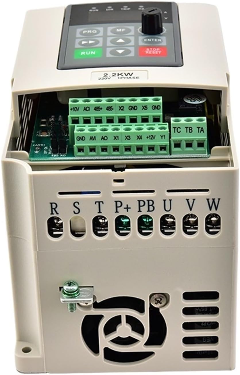
Image 4.1: Top view of the VFD with the protective cover removed, revealing the power and control terminal blocks for wiring connections.

Image 4.2: Example wiring diagram showing connections from a circuit breaker to the VFD's input terminals (R, S, T) and from the VFD's output terminals (U, V, W) to a three-phase motor. Control terminals are also visible.
Power Input (R, S, T):
Connect the main power supply to these terminals. For the 1PH220VAC model, connect the single-phase input to R and S, leaving T unused or bridged as per specific model instructions. Ensure proper grounding.
Motor Output (U, V, W):
Connect the motor's three-phase windings to these terminals. Ensure correct phase sequence for desired motor rotation.
Control Terminals:
These terminals are for external control signals such as start/stop commands, speed reference (e.g., 0-10V, 4-20mA), and fault indicators. Refer to the detailed wiring diagram for specific terminal functions.
5. Operating Instructions
5.1. Control Panel Functions
- RUN: Starts the motor.
- STOP/RESET: Stops the motor or clears fault indications.
- PRG (Program): Enters or exits the parameter setting mode.
- MF (Multi-Function): Used for various functions depending on the context.
- ▲ / ▼ (Up/Down Arrows): Navigates through parameters or adjusts values.
- ENTER: Confirms selections or saves parameter changes.
- Potentiometer: Adjusts the output frequency/motor speed.
5.2. Basic Operation
- Power On: Apply power to the VFD. The display will illuminate.
- Set Speed: Adjust the potentiometer to the desired frequency/speed.
- Start Motor: Press the RUN button. The motor will accelerate to the set speed.
- Stop Motor: Press the STOP/RESET button. The motor will decelerate and stop.
6. Parameter Settings
The VFD has numerous parameters that can be configured to optimize performance for specific applications. These include motor parameters, acceleration/deceleration times, maximum/minimum frequencies, and control modes.
To access parameters:
- Press the PRG button to enter parameter mode.
- Use the ▲ / ▼ arrow buttons to navigate through parameter groups and individual parameters.
- Press ENTER to view or edit a parameter's value.
- Use the ▲ / ▼ arrow buttons to change the value.
- Press ENTER again to save the new value.
- Press PRG to exit parameter mode.
Refer to the comprehensive parameter list provided with your VFD for detailed descriptions and recommended settings for each parameter.
7. Maintenance
Regular maintenance ensures the longevity and reliable operation of your VFD.
- Cleaning: Periodically clean the VFD's exterior and cooling vents to prevent dust accumulation, which can hinder heat dissipation. Use a soft, dry cloth. Do not use liquid cleaners.
- Inspection: Regularly inspect all wiring connections for tightness and signs of wear or damage. Check the cooling fan for proper operation and obstructions.
- Environment: Ensure the operating environment remains within the specified temperature and humidity ranges.
Always disconnect power before performing any maintenance.
8. Troubleshooting
If you encounter issues with your VFD, refer to the following common problems and solutions:
| Problem | Possible Cause | Solution |
|---|---|---|
| Motor does not run | No power, incorrect wiring, fault condition, stop command active | Check power supply, verify wiring, clear fault (STOP/RESET), check control signals |
| VFD displays an error code | Overcurrent, overvoltage, undervoltage, overload, overheating | Refer to the VFD's specific error code list for diagnosis and resolution. Address the underlying cause (e.g., reduce load, check input voltage). |
| Motor speed is unstable | Incorrect motor parameters, unstable input voltage, poor grounding | Verify motor parameters in VFD settings, check power supply stability, ensure proper grounding. |
| VFD overheats | Insufficient ventilation, excessive ambient temperature, VFD overloaded | Improve ventilation, reduce ambient temperature, check motor load, ensure VFD is adequately sized. |
For persistent issues or complex problems, contact technical support.
9. Specifications
The following table outlines the key technical specifications for the GHHSBO ZA-D12 VFD (1.5KW, 1PH220VAC-3PH220VAC model):
| Feature | Specification |
|---|---|
| Model Number | ZA-D12 |
| Power Rating | 1.5KW (also available in 0.4KW, 0.75KW, 2.2KW) |
| Input Voltage | 1PH 220VAC (also available in 3PH 220VAC, 3PH 380VAC) |
| Output Voltage | 3PH 220VAC (matches input voltage configuration) |
| Output Frequency | 0-999.99Hz |
| Type | DC/AC Inverter |
| Output Type | Triple Phase |
| Item Weight | 50 Grams (approx. 1.76 ounces) |
| Package Dimensions | 0.39 x 0.39 x 0.39 inches |
10. Warranty and Support
For warranty information, please refer to the terms and conditions provided at the time of purchase or contact your seller directly. For technical support or further assistance, please reach out to the manufacturer or authorized service center.


