1. Introduction
The INGCO DM310002 is a True RMS 6000-count digital multimeter designed for precise electrical measurements. It offers a wide range of functions including AC/DC voltage, AC/DC current, resistance, diode test, continuity, non-contact voltage (NCV) detection, data hold, and features a built-in flashlight and backlight for enhanced visibility. This manual provides essential information for safe and effective operation of your multimeter.
2. Safety Information
Always adhere to safety precautions when using any electrical testing equipment. Failure to do so may result in electric shock, injury, or damage to the meter or equipment under test.
- Do not exceed the maximum input limits for any function.
- Inspect test leads for damaged insulation or exposed metal before use.
- Do not use the meter if it appears damaged or if the case is open.
- Exercise extreme caution when working with voltages above 30V AC RMS, 42V peak, or 60V DC. These voltages pose a shock hazard.
- Remove test leads from the circuit before changing functions.
- Replace the battery immediately when the low battery indicator appears.
- Do not operate the meter in explosive gas, vapor, or dust.
3. Product Overview
The INGCO DM310002 Digital Multimeter features a clear display and intuitive controls for various electrical measurements.
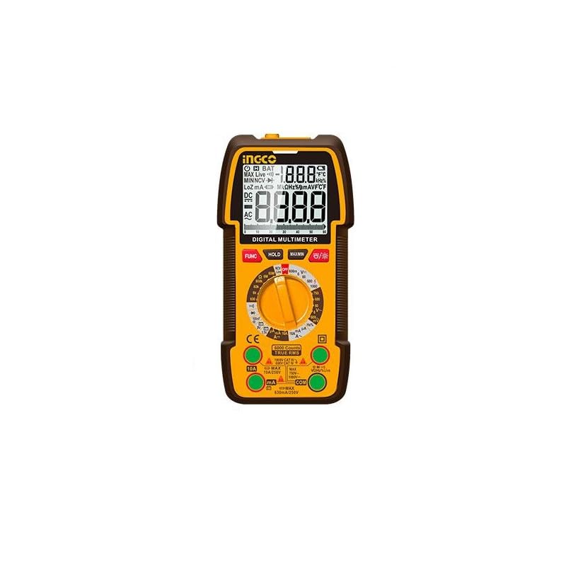
Figure 1: INGCO DM310002 Digital Multimeter showing its front panel, display, rotary switch, input jacks, and approximate dimensions (188mm height, 90mm width, 58mm depth).
3.1 Display Features
- True RMS 6000 Counts: Provides accurate readings for non-sinusoidal waveforms.
- Backlight: Improves visibility in low-light conditions.
- Data Hold: Freezes the current reading on the display.
- NCV Indicator: Non-Contact Voltage detection.
- Low Battery Indicator: Alerts when battery replacement is needed.
3.2 Controls and Input Jacks
- Rotary Switch: Selects the desired measurement function.
- FUNC Button: Toggles between different measurement modes within a single rotary switch position (e.g., AC/DC, Diode/Continuity).
- HOLD Button: Activates/deactivates data hold.
- MAX/MIN Button: Records maximum and minimum values during a measurement.
- Backlight/Flashlight Button: Activates the display backlight and the built-in flashlight.
- VΩmA Input Jack: Positive input for voltage, resistance, and milliampere current measurements.
- COM Input Jack: Common (negative) input for all measurements.
- 10A Input Jack: Positive input for high current (up to 10A) measurements.
4. Setup
4.1 Battery Installation
The DM310002 requires batteries for operation. To install or replace batteries:
- Ensure the multimeter is turned off and test leads are disconnected.
- Locate the battery compartment cover on the back of the meter.
- Unscrew the retaining screw(s) and remove the cover.
- Insert new batteries, observing correct polarity (+ and -).
- Replace the battery compartment cover and secure it with the screw(s).
4.2 Connecting Test Leads
Always connect the black test lead to the COM jack. Connect the red test lead to the appropriate input jack based on the measurement type:
- For voltage, resistance, diode, continuity, and milliampere current: Connect the red lead to the VΩmA jack.
- For 10A current: Connect the red lead to the 10A jack.
5. Operating Instructions
Before taking any measurement, ensure the test leads are correctly connected and the rotary switch is set to the desired function.
5.1 Measuring DC/AC Voltage
- Connect the red test lead to the VΩmA jack and the black test lead to the COM jack.
- Set the rotary switch to the V~ (AC Voltage) or V- (DC Voltage) position. If the symbol is combined, press the FUNC button to select AC or DC.
- Connect the test leads in parallel across the circuit or component to be measured.
- Read the voltage value on the display.
5.2 Measuring DC/AC Current (up to 10A)
Caution: Never connect the meter in parallel to a voltage source when measuring current. This can blow the fuse or damage the meter.
- For currents up to 600mA: Connect the red test lead to the VΩmA jack.
- For currents up to 10A: Connect the red test lead to the 10A jack.
- Connect the black test lead to the COM jack.
- Set the rotary switch to the appropriate A~ (AC Current) or A- (DC Current) position. Press FUNC if needed.
- Open the circuit where current is to be measured and connect the meter in series with the load.
- Read the current value on the display.
5.3 Measuring Resistance
- Connect the red test lead to the VΩmA jack and the black test lead to the COM jack.
- Set the rotary switch to the Ω (Resistance) position.
- Ensure the circuit under test is de-energized.
- Connect the test leads across the component to be measured.
- Read the resistance value on the display.
5.4 Diode Test and Continuity
- Connect the red test lead to the VΩmA jack and the black test lead to the COM jack.
- Set the rotary switch to the Diode/Continuity position. Press FUNC to toggle between diode test and continuity.
- For Diode Test: Connect the red lead to the anode and the black lead to the cathode of the diode. The display will show the forward voltage drop. Reverse the leads; the display should show OL (Open Loop) for a good diode.
- For Continuity Test: Connect the test leads across the circuit or component. If continuity exists (resistance below a certain threshold), the buzzer will sound.
5.5 NCV (Non-Contact Voltage) Detection
- Set the rotary switch to the NCV position.
- Move the top part of the meter near a live AC voltage source.
- The meter will beep and the NCV indicator will light up, indicating the presence of AC voltage.
5.6 Data Hold, MAX/MIN, Backlight/Flashlight
- HOLD: Press the HOLD button to freeze the current reading on the display. Press again to release.
- MAX/MIN: Press the MAX/MIN button to enter MAX/MIN recording mode. The meter will display the maximum or minimum value detected. Press again to cycle through MAX, MIN, and exit.
- Backlight/Flashlight: Press the Backlight/Flashlight button to turn on the display backlight. Press and hold to activate the built-in flashlight. Press again to turn off.
6. Maintenance
6.1 Cleaning
Wipe the meter with a damp cloth and mild detergent. Do not use abrasives or solvents. Ensure the meter is completely dry before use.
6.2 Battery Replacement
When the low battery indicator appears on the display, replace the batteries as described in Section 4.1. Use the specified battery type.
6.3 Storage
If the meter is not used for an extended period, remove the batteries to prevent leakage and damage. Store the meter in a cool, dry place.
7. Troubleshooting
- No display or faint display: Check battery installation and charge level. Replace batteries if necessary.
- "OL" displayed: Indicates an overload or open circuit. Check connections and ensure the measurement range is appropriate.
- Incorrect readings: Verify the correct function is selected, test leads are properly connected, and the circuit is within the meter's specified range.
- No continuity beep: Ensure the function is set to continuity and the resistance is below the threshold for continuity.
8. Specifications
| Feature | Specification |
|---|---|
| Display | True RMS 6000 Counts Digital Display |
| DC Voltage Range | 600mV / 6V / 60V / 600V / 1000V |
| AC Voltage Range | 600mV / 6V / 60V / 600V / 750V |
| DC Current Range | 6000µA / 60mA / 600mA / 10A |
| AC Current Range | 6000µA / 60mA / 600mA / 10A |
| Resistance Range | Yes (Specific ranges not detailed in source, typical for 6000 counts) |
| Diode Test | Yes |
| Continuity Test | Yes |
| NCV (Non-Contact Voltage) | Yes |
| Data Hold | Yes |
| Flashlight | Built-in |
| Backlight | Yes |
| Power Source | Battery Powered (Batteries Required) |
| Dimensions | 10 x 20 x 37 cm (approximate) |
| Weight | 209 g (0.21 kg) |
| Safety Rating | CAT III 1000V (implied by 1000V DC max) |
9. Warranty and Support
For warranty information and technical support, please refer to the documentation provided with your purchase or contact your local INGCO distributor. Keep your purchase receipt as proof of purchase for warranty claims.


