1. Introduction
This manual provides essential information for the safe and effective installation, operation, and maintenance of your IIUUAYUVI Industrial Plugs and Sockets. Please read this manual thoroughly before use and retain it for future reference. These industrial connectors are designed for robust electrical connections in various environments, offering different current ratings, voltages, pin configurations, and ingress protection levels.
2. Safety Information
WARNING: Electrical shock hazard. Improper installation or use can result in serious injury or death. Always follow local electrical codes and safety regulations.
- Installation should only be performed by a qualified electrician.
- Ensure power is disconnected before any installation, wiring, or maintenance.
- Verify that the voltage and current ratings of the plug/socket match the electrical system and connected equipment.
- Do not use damaged plugs or sockets. Inspect for cracks, corrosion, or loose parts before each use.
- Ensure proper grounding according to wiring diagrams and local codes.
- Do not expose non-IP67 rated connectors to excessive moisture or water.
- Keep children away from electrical connections.
3. Product Overview
The IIUUAYUVI Industrial Plugs and Sockets are available in various configurations, including 3-pin, 4-pin, and 5-pin designs, with current ratings of 16A or 32A, and suitable for 220V or 380V systems. They feature IP44 (splash-proof) or IP67 (waterproof) ratings for different environmental needs.

Figure 3.1: Overview of various IIUUAYUVI industrial plugs and sockets, illustrating different pin counts (3P, 4P, 5P) and ingress protection ratings (IP44, IP67) for both male plugs and female sockets.
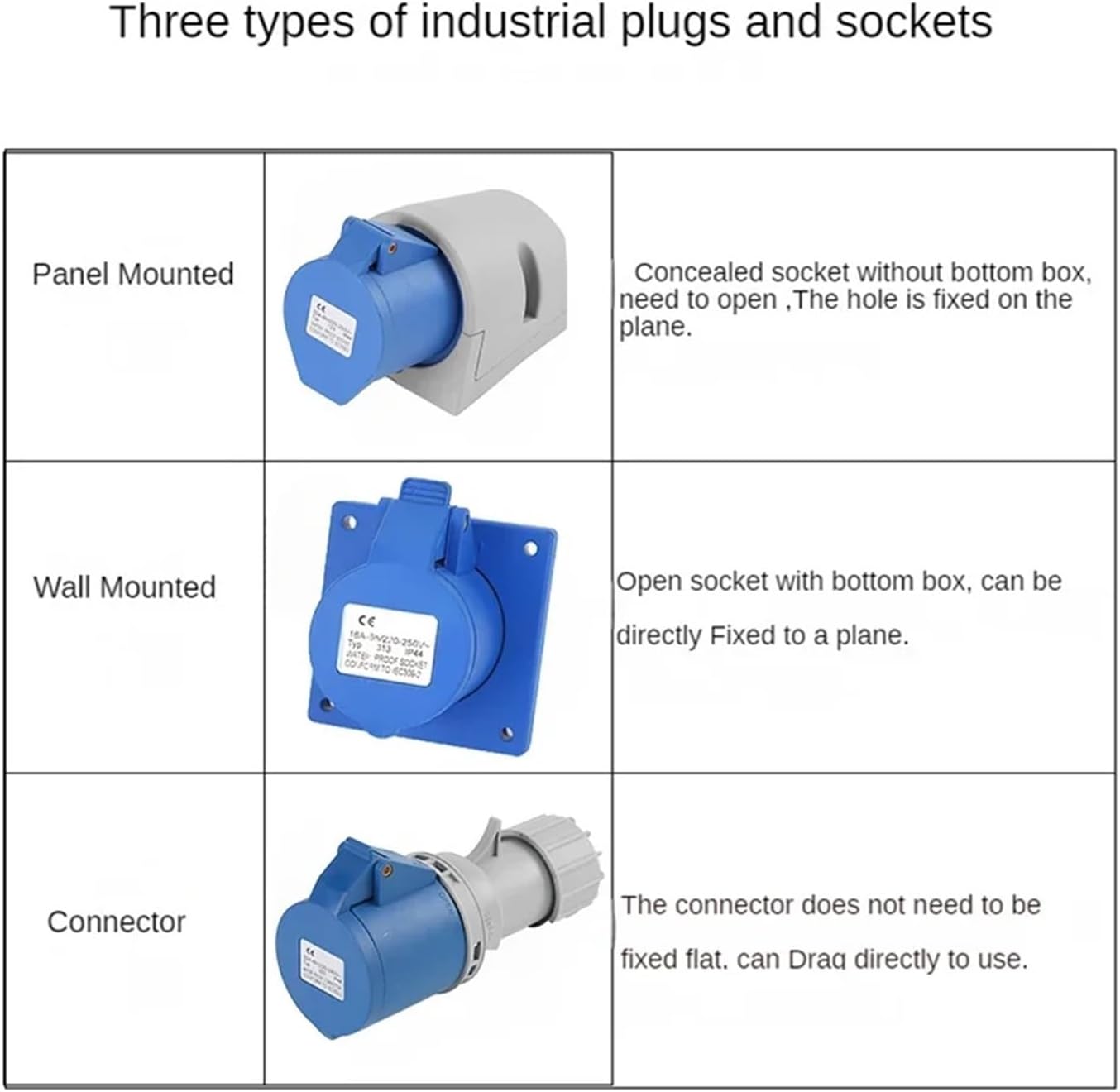
Figure 3.2: Illustration of three common types of industrial sockets: Panel Mounted (concealed, fixed on a plane), Wall Mounted (open, directly fixed to a plane), and Connector (portable, not fixed).

Figure 3.3: Detailed breakdown of an industrial plug, showing key features such as the rear waterproof inlet hole, National Standard Brass terminals for reliable conductivity, an anti-shedding buckle for secure connection, and construction from flame retardant engineering plastics for safety.
4. Setup and Installation
Proper installation is critical for safety and performance. Refer to Figure 3.3 for component identification.
- Preparation: Disconnect all power to the circuit where the plug or socket will be installed. Gather necessary tools (wire strippers, screwdrivers, multimeter).
- Disassembly: Unscrew the housing of the plug or socket to access the internal terminals. For plugs, loosen the anti-shedding buckle and remove the cable gland.
- Cable Entry: For plugs, feed the appropriate electrical cable through the rear waterproof inlet hole and cable gland. Ensure the cable diameter matches the gland for a tight, waterproof seal.
- Wire Stripping: Carefully strip the outer jacket of the cable, then strip approximately 8-10mm of insulation from each individual conductor.
- Wiring: Connect each conductor to its corresponding National Standard Brass terminal. Typically, the green/yellow wire is for ground (earth), blue for neutral, and brown/black/grey for live phases. Ensure all strands are securely clamped by the terminal screws. Double-check polarity.
- Assembly: Reassemble the plug/socket housing, ensuring all seals (especially for IP67 models) are correctly seated. Tighten all screws firmly, but do not overtighten. For plugs, secure the cable with the anti-shedding buckle and tighten the cable gland to ensure strain relief and waterproof integrity.
- Mounting (for Sockets): For Panel Mounted sockets, fix the concealed socket into the designated opening on a panel. For Wall Mounted sockets, directly fix the open socket with its bottom box to a flat surface using appropriate fasteners.
- Testing: Before restoring power, use a multimeter to check for continuity and ensure there are no short circuits or incorrect wiring. Once verified, restore power and test the connection.
5. Operating Instructions
To operate, align the male plug with the female socket, ensuring the keyways match. Insert the plug firmly into the socket until it is fully seated. For IP67 models, ensure the sealing cap is properly closed when not in use to maintain water and dust protection. To disconnect, firmly grasp both the plug and socket and pull them apart. Do not pull by the cable.
6. Maintenance
Regular maintenance ensures longevity and safe operation.
- Inspection: Periodically inspect plugs and sockets for any signs of physical damage, such as cracks, discoloration, or corrosion on the terminals. Check for loose connections or frayed cables.
- Cleaning: Disconnect power before cleaning. Use a dry, clean cloth to wipe down the exterior. For stubborn dirt, a slightly damp cloth can be used, ensuring the connector is completely dry before reconnecting to power. Do not use abrasive cleaners or solvents.
- Seals: For IP67 rated connectors, regularly check the integrity of rubber seals and gaskets. Replace if they show signs of wear, cracking, or hardening to maintain waterproof protection.
- Tightness: Periodically check and retighten terminal screws and housing screws, as vibrations can cause them to loosen over time.
7. Troubleshooting
If you encounter issues, perform the following basic checks:
- No Power:
- Check if the power source is active (e.g., circuit breaker tripped).
- Ensure the plug is fully inserted into the socket.
- Inspect the cable for damage or breaks.
- Verify internal wiring connections are secure (with power disconnected).
- Loose Connection:
- Ensure the plug and socket are fully engaged.
- Check for any debris preventing a full connection.
- Inspect terminals for corrosion or deformation.
- Overheating:
- Disconnect immediately.
- This could indicate an overload, loose connection, or damaged component. Do not use until the cause is identified and rectified by a qualified professional.
If problems persist after these checks, consult a qualified electrician or contact the manufacturer for assistance.
8. Specifications
| Feature | Detail |
|---|---|
| Model Number | 3P/4P/5P (Pin configurations) |
| Voltage Rating | 220V / 380V |
| Current Rating | 16A / 32A |
| Ingress Protection (IP) Rating | IP44 (Splash-proof) / IP67 (Waterproof) |
| Material | Flame Retardant Engineering Plastics, National Standard Brass Terminals |
| Item Weight | Approximately 9.9 ounces (for 5 PCS IP44-4P 32a Connector variant) |
| Package Dimensions | Approximately 0.39 x 0.39 x 0.39 inches |
| Assembly Required | Yes (for wiring) |
9. Warranty and Support
Specific warranty information for this product is not provided in the available data. For details regarding warranty coverage, technical support, or replacement parts, please contact the manufacturer, IIUUAYUVI, or your point of purchase directly. Always provide your product model number (B0F6V2C847) when seeking support.