1. Introduction
This manual provides essential instructions for the safe and effective operation of your Fafeicy PM2118 Clamp Multimeter. Please read this manual thoroughly before use and retain it for future reference. This device is designed for measuring AC/DC current, AC/DC voltage, frequency, impedance, capacitance, and temperature.
Safety Information
- Always ensure the multimeter is in the correct function mode before connecting to a circuit.
- Do not attempt to measure voltages or currents exceeding the specified maximum limits.
- Exercise extreme caution when working with live circuits. High voltages can cause severe injury or death.
- Inspect test leads for damage before each use. Do not use if insulation is compromised.
- Replace batteries promptly when the low battery indicator appears to ensure accurate readings.
- Do not operate the multimeter in wet environments or explosive atmospheres.
2. Package Contents
Verify that all items listed below are present in your package:
- 1 x Fafeicy PM2118 Clamp Multimeter
- 2 x Test Probes (Red and Black)
- 1 x Thermocouple (for temperature measurement)
- 1 x Black Storage Bag
- 1 x User Manual (this document)
3. Product Overview
Familiarize yourself with the components of your PM2118 Clamp Multimeter.

Figure 3.1: Labeled diagram of the PM2118 Clamp Multimeter, showing the clamp, clamp trigger, function knob, data hold/backlight button, surge/NCV measurement button, LCD screen, and probe ports.
- Clamp: Used for non-contact AC current measurement.
- Clamp Trigger: Opens and closes the clamp jaws.
- Function Knob: Selects the desired measurement function (e.g., ACV, DCV, Resistance, Frequency, Temperature).
- Data Hold/Backlight Button: Freezes the current reading on the display or activates the backlight.
- NCV (Non-Contact Voltage) Button: Activates the non-contact voltage detection feature.
- LCD Screen: Displays measurement readings and indicators.
- Probe Ports: Connect test leads for voltage, resistance, capacitance, and other measurements.

Figure 3.2: Close-up view of the multimeter's function knob, highlighting the various measurement functions available for selection.
4. Setup
4.1 Battery Installation
The PM2118 Clamp Multimeter requires two 1.5V AAA batteries (not included).
- Ensure the multimeter is turned OFF.
- Locate the battery compartment cover on the back of the device.
- Use a screwdriver to loosen the screw securing the battery cover.
- Remove the battery cover.
- Insert two 1.5V AAA batteries, observing the correct polarity (+ and -) as indicated inside the compartment.
- Replace the battery cover and tighten the screw securely.

Figure 4.1: View of the battery compartment on the back of the multimeter, illustrating the process of battery installation.
5. Operating Instructions
This section details how to perform various measurements with your PM2118 Clamp Multimeter.
5.1 AC/DC Voltage Measurement (V~)
- Turn the function knob to the "V~" position for AC voltage or "V=" for DC voltage.
- Insert the red test lead into the "VΩHz" input jack and the black test lead into the "COM" input jack.
- Connect the test probes in parallel across the circuit or component you wish to measure.
- Read the voltage value displayed on the LCD screen.

Figure 5.1: Example of measuring socket voltage using the test probes.
5.2 AC Current Measurement (A~)
The clamp function is used for non-contact AC current measurement.
- Turn the function knob to the "A~" position.
- Press the clamp trigger to open the jaws.
- Enclose only one conductor of the circuit within the clamp jaws. Ensure the jaws are fully closed.
- Read the AC current value displayed on the LCD screen.

Figure 5.2: Close-up of the clamp jaws, used for non-contact AC current measurement.
5.3 Resistance Measurement (Ω)
- Turn the function knob to the "Ω" position.
- Insert the red test lead into the "VΩHz" input jack and the black test lead into the "COM" input jack.
- Ensure the circuit or component is de-energized before measuring resistance.
- Connect the test probes across the component.
- Read the resistance value displayed on the LCD screen.

Figure 5.3: Example of measuring small resistance using the test probes.
5.4 Capacitance Measurement (F)
- Turn the function knob to the "F" position.
- Insert the red test lead into the "VΩHz" input jack and the black test lead into the "COM" input jack.
- Ensure the capacitor is fully discharged before measurement to prevent damage to the multimeter.
- Connect the test probes across the capacitor terminals.
- Read the capacitance value displayed on the LCD screen.
5.5 Frequency Measurement (Hz)
- Turn the function knob to the "Hz" position.
- Insert the red test lead into the "VΩHz" input jack and the black test lead into the "COM" input jack.
- Connect the test probes in parallel across the signal source.
- Read the frequency value displayed on the LCD screen.
5.6 Temperature Measurement (°C/°F)
- Turn the function knob to the "°C/°F" position.
- Connect the thermocouple to the appropriate input jacks (usually marked TEMP or similar, or use the VΩHz and COM ports if specified by the device).
- Place the tip of the thermocouple on or in the object whose temperature you wish to measure.
- Read the temperature value displayed on the LCD screen.

Figure 5.4: Example of temperature measurement using the provided thermocouple.
5.7 Non-Contact Voltage (NCV) Detection
- Press the "NCV" button.
- Move the top end of the multimeter near a live conductor.
- The multimeter will emit an audible beep and/or flash an indicator light when AC voltage is detected, indicating the presence of a live wire without direct contact.
5.8 Continuity Test
- Turn the function knob to the continuity symbol (usually a speaker icon).
- Insert the red test lead into the "VΩHz" input jack and the black test lead into the "COM" input jack.
- Connect the test probes across the component or circuit path.
- If the circuit is continuous (low resistance), the multimeter will emit an audible beep.
5.9 Data Hold Function
Press the "HOLD" button (often combined with backlight) to freeze the current reading on the display. Press it again to release the hold function.
5.10 Backlight Function
Press and hold the "HOLD" button for a few seconds to activate the display backlight. Press and hold again to turn it off.
6. Maintenance
6.1 Cleaning
Wipe the multimeter casing with a damp cloth and mild detergent. Do not use abrasive cleaners or solvents. Ensure the device is dry before storage or next use.
6.2 Battery Replacement
Refer to Section 4.1 for battery installation instructions. Replace batteries when the low battery indicator appears on the display to maintain measurement accuracy.
6.3 Storage
When not in use for extended periods, remove the batteries to prevent leakage. Store the multimeter in its protective bag in a cool, dry place, away from direct sunlight and extreme temperatures.
7. Troubleshooting
| Problem | Possible Cause | Solution |
|---|---|---|
| No display or dim display | Dead or low batteries; incorrect battery polarity. | Replace batteries, ensuring correct polarity. |
| Inaccurate readings | Incorrect function selected; damaged test leads; low battery; external interference. | Verify function knob setting; check test leads for damage; replace batteries; move away from strong electromagnetic fields. |
| No continuity beep | Open circuit; high resistance; incorrect function. | Ensure circuit is closed; check for breaks; verify function knob is on continuity. |
| Clamp measurement not working | Incorrect function; jaws not fully closed; measuring DC current (clamp is for AC only). | Ensure function knob is on AC current; close jaws completely; use test leads for DC current if applicable. |
8. Specifications
| Parameter | Value |
|---|---|
| Model | PM2118 |
| Power Supply | 2 x 1.5V AAA batteries (not included) |
| Dimensions (L x W x H) | 187 x 65 x 38 mm (7.3 x 2.5 x 1.5 inches) |
| Weight | Approx. 357g (12.6 ounces) |
| Measurement Functions | AC/DC Current, AC/DC Voltage, Frequency, Impedance, Capacitance, Temperature |
| Special Features | Non-Contact Voltage (NCV) Detection, Continuity Test, Data Hold, Auto Power Off, Backlight |
| Safety Rating | 600V CAT III |
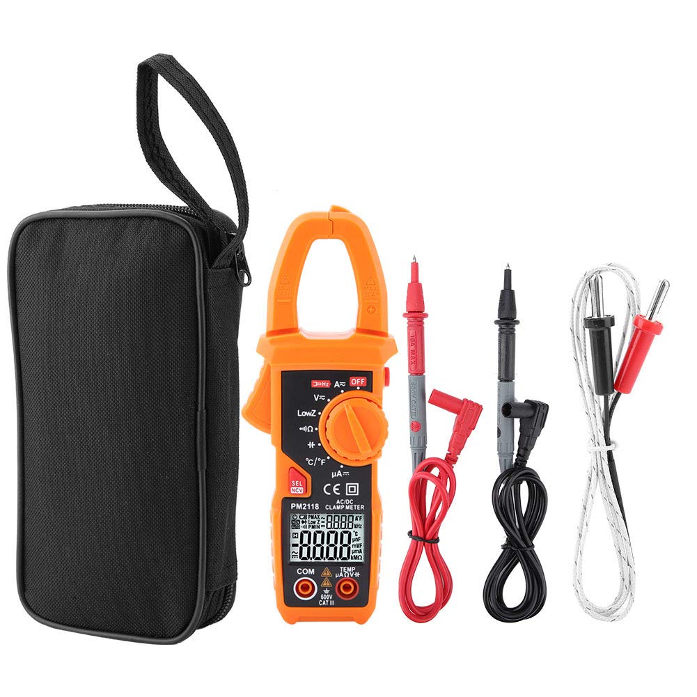
Figure 8.1: Dimensions of the PM2118 Clamp Multimeter.
9. Warranty and Support
Fafeicy products are designed for reliability and performance. For warranty information or technical support, please contact your retailer or the manufacturer directly. Please have your product model number (PM2118) and purchase date available when seeking support.
For further assistance, please visit the official Fafeicy store or contact their customer service department.